


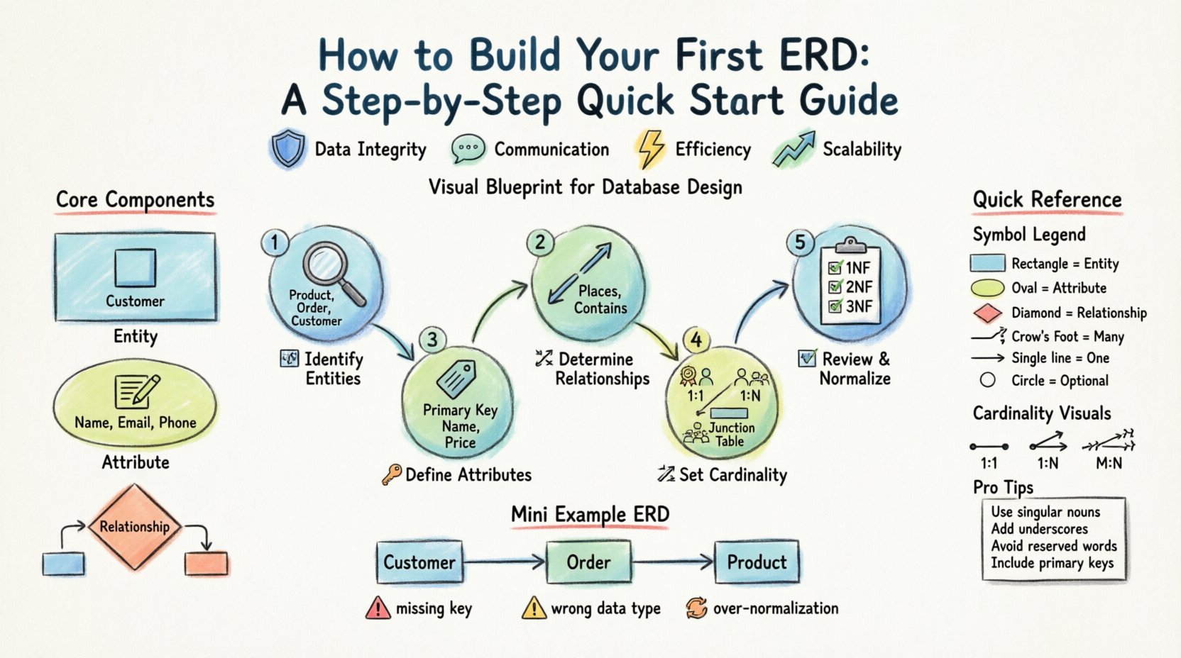
Designing a robust database is foundational to any software application. Without a structured plan, data becomes scattered, difficult to query, and prone to errors. An Entity Relationship Diagram (ERD) serves as the blueprint for this structure. It visualizes how data entities interact, ensuring integrity before a single line of code is written. This guide walks you through the process of creating your first ERD, focusing on core concepts, notation, and practical steps.
Understanding the Entity Relationship Diagram 📊
An ERD is a visual representation of a database schema. It maps out the entities, their attributes, and the relationships between them. Think of it as a map for your data. Just as a road map helps you navigate from point A to point B, an ERD helps your database management system navigate relationships between tables.
Why is this important?
- Data Integrity: It ensures that data remains consistent and accurate across the system.
- Communication: It provides a common language for developers, database administrators, and stakeholders.
- Efficiency: It helps identify redundancy early, saving time during the implementation phase.
- Scalability: A well-designed schema allows the database to grow without requiring a complete overhaul.
Core Components of an ERD
Before drawing lines and boxes, you must understand the building blocks. Every diagram relies on these three fundamental elements.
- Entity: A real-world object or concept about which data is stored. Examples include Customer, Order, or Product.
- Attribute: A specific property or characteristic of an entity. For a Customer, attributes might include Name, Email, and Phone Number.
- Relationship: The association between two or more entities. This defines how data in one entity connects to data in another.
Common ERD Symbols and Notation 🛠️
There are different ways to represent these components visually. The two most common styles are Chen notation and Crow’s Foot notation. While Chen notation uses rectangles and diamonds, Crow’s Foot uses rectangles and lines with specific ends. Most modern database modeling tools utilize variations of Crow’s Foot.
| Symbol | Meaning | Usage Example |
|---|---|---|
| Rectangle | Represents an Entity | A box labeled Student |
| Oval | Represents an Attribute | An oval connected to Student labeled ID |
| Diamond | Represents a Relationship | A diamond connecting Student and Course |
| Line with Crow’s Foot | Indicates “Many” (M) | One student can take many courses |
| Line with Single Tick | Indicates “One” (1) | A course has one instructor |
| Circle | Indicates Optional Participation | A student might not have an assigned ID yet |
Step-by-Step Guide to Building Your First ERD 🚀
Constructing an ERD is a logical process. You do not need to know the final code to start. You need to understand the business requirements. Follow these steps to create a solid foundation.
Step 1: Identify the Entities 📦
The first task is to list every distinct object in your system. Look at your business requirements document or interview the stakeholders to find nouns. These nouns are usually your entities.
- Scan for Nouns: If you are building a library system, look for words like Book, Member, Loan, and Fine.
- Filter Out Irrelevant Items: Not every noun is an entity. Words like Processing or Checking are usually actions, not entities.
- Keep it Granular: Avoid combining multiple concepts into one box. A CustomerAddress entity might eventually need to be split into Customer and Address if you need to track multiple addresses.
Example List:
- Product
- Supplier
- Order
- Customer
Step 2: Define the Attributes 🏷️
Once entities are identified, you must determine what information you need to store about them. Attributes are the columns in your eventual database table.
- Primary Keys: Every entity needs a unique identifier. This is usually an ID field (e.g.,
CustomerID,ProductID). It must be unique for every record. - Descriptive Attributes: These describe the entity. For a Product, this includes Name, Price, and StockQuantity.
- Foreign Keys: These will be identified later during the relationship step, but note where data will link to other tables.
Best Practice: Avoid storing calculated values as attributes (e.g., TotalPrice). Calculate these at runtime to prevent data inconsistency.
Step 3: Determine the Relationships 🔗
Now you connect the entities. This step defines how data interacts. Ask questions like: Can one Customer have multiple Orders? Can one Order belong to multiple Customers?
- Identify Associations: Look for verbs in your requirements. Places, Contains, Supplies.
- Define Direction: Determine if the relationship is one-way or bidirectional.
- Check for Transitivity: Ensure relationships are direct. If A relates to B, and B relates to C, check if A needs a direct link to C.
Step 4: Establish Cardinality and Participation 📏
Cardinality defines the number of instances of one entity that relate to instances of another. This is crucial for defining foreign key constraints.
Types of Cardinality
- One-to-One (1:1): One instance of Entity A relates to exactly one instance of Entity B. Example: One Employee has one EmployeeBadge.
- One-to-Many (1:N): One instance of Entity A relates to many instances of Entity B. Example: One Manager supervises many Employees.
- Many-to-Many (M:N): Many instances of Entity A relate to many instances of Entity B. Example: Many Students enroll in many Courses.
Participation Constraints
- Mandatory: An entity must participate in the relationship. Every Order must have a Customer.
- Optional: An entity does not have to participate. A Customer might not have a Shipping Address if they only pay in-store.
Note on Many-to-Many: Most relational databases cannot store Many-to-Many relationships directly. You must resolve them by creating a junction table (or bridge table). For Students and Courses, create a table called Enrollments that links StudentID and CourseID.
Step 5: Review and Normalize 🧹
After drawing the connections, review your diagram for structural flaws. Normalization is the process of organizing data to reduce redundancy and improve integrity.
- First Normal Form (1NF): Ensure every column contains atomic values. No lists or arrays in a single cell.
- Second Normal Form (2NF): Ensure all non-key attributes are fully dependent on the primary key. Remove partial dependencies.
- Third Normal Form (3NF): Ensure no transitive dependencies exist. Remove attributes that depend on other non-key attributes.
While you do not need to go beyond 3NF for most applications, ensuring your design adheres to these rules prevents data anomalies.
Common Pitfalls to Avoid ⚠️
Even experienced designers make mistakes. Being aware of common errors can save you from major refactoring later.
- Missing Primary Keys: Never create a table without a unique identifier. It makes updating and deleting records nearly impossible.
- Incorrect Data Types: Ensure attributes match the data. Do not store dates as text. Do not store prices as integers if you need cents.
- Over-Normalization: While normalization is good, too many tables can make queries slow and complex. Balance integrity with performance.
- Ignoring Case Sensitivity: Decide early if your system is case-sensitive. [email protected] should not be treated differently than [email protected].
- Hardcoded Values: Avoid storing status codes like
1or2without a reference table. Use a lookup table for statuses like Active, Inactive, Pending.
Best Practices for Naming Conventions 📝
Consistency in naming makes your ERD and the resulting database readable for everyone involved. A confusing name leads to confusion in code.
- Use Singular Nouns: Name tables in the singular form (e.g., Customer instead of Customers).
- Use Underscores: Separate words with underscores for readability (e.g.,
customer_nameinstead ofcustomername). - Avoid Reserved Words: Do not use keywords like Order, User, or Group as table names without modification, as they may conflict with SQL syntax.
- Be Descriptive: Use clear names.
cust_idis okay, butcustomer_idis better for clarity. - Standardize Prefixes: If using specific schemas, maintain prefixes (e.g.,
tbl_orref_).
Visualizing the Data Flow 🔄
Once your diagram is complete, visualize how data moves through the system. This helps in understanding the application logic.
- Insertion: How does new data enter the primary entity? (e.g., a new Customer record).
- Modification: How does data update? (e.g., changing an address).
- Deletion: What happens to related data when a record is deleted? (e.g., Cascade delete vs. Restrict).
- Querying: How will you retrieve data? (e.g., Joining Order and Customer tables).
Tools for Diagramming 🖥️
While you can draw on paper, digital tools offer advantages like version control and automatic SQL generation. When selecting a tool, look for features that support standard ERD notations.
- Collaboration: Can multiple users edit the diagram simultaneously?
- Export Options: Can you export to SQL scripts, PNG, or PDF?
- Validation: Does the tool check for normalization rules or circular dependencies?
- Integration: Does it integrate with your existing workflow or project management tools?
Frequently Asked Questions ❓
Here are answers to common questions beginners often ask when starting with database design.
1. Do I need to know SQL before making an ERD?
No. An ERD is a design tool. You can create the logical structure without writing SQL. The diagram helps you understand what SQL you will eventually need to write.
2. Can an ERD change later?
Yes, but it should be minimized. Changing an ERD after the database is populated can be costly and risky. It is best to finalize the design before deployment.
3. What is the difference between Logical and Physical ERD?
- Logical ERD: Focuses on entities and relationships without worrying about specific database software details.
- Physical ERD: Includes specific data types, indexes, and constraints required for a specific database management system.
4. How many tables is too many?
There is no fixed number. It depends on complexity. However, if you find yourself creating too many tables for a simple application, you may be over-normalizing.
5. Should I include non-relational data?
Standard ERDs are for relational data. If you are designing a document store or graph database, the concepts differ slightly. This guide focuses on relational models.
Final Thoughts 🎯
Building your first ERD requires patience and attention to detail. It is not just about drawing shapes; it is about modeling real-world logic into a structured format. By following the steps outlined above, you ensure that your database will be scalable, efficient, and easy to maintain.
Start small. Map out a simple system first. Practice identifying entities and relationships. As you gain experience, you will find that designing complex systems becomes intuitive. Remember, a good database design is invisible to the user but critical to the success of the application.
Take your time with the normalization phase. It is the most technical part of the process, but it pays off in data quality. Use the symbols and conventions discussed here to keep your diagrams clear. With a solid ERD in hand, you are ready to move forward with implementation.