Building a robust information system is less about writing code and more about understanding structure. Before a single line of script is executed, before a single table is created, the foundation must be laid. This foundation is the Entity-Relationship Diagram, commonly known as the ERD. 🏗️ It is not merely a drawing; it is a logical blueprint that dictates how data flows, connects, and persists. Many developers rush past this stage, treating it as a formality. This is a critical error. The logic hidden within an ERD determines the performance, scalability, and integrity of the entire application.
This guide explores the fundamental mechanics of database modeling. We will move beyond simple definitions to understand the underlying logic that governs data relationships. By the end, you will see why starting here is not just a recommendation, but a necessity for any serious technical endeavor.
🔍 What Is an ERD and Why Does It Matter?
An Entity-Relationship Diagram is a visual representation of the structure of a database. It maps out the entities (objects or concepts) and the relationships between them. While it seems straightforward, the depth lies in the precision of these mappings. 📊
Consider the alternative: creating tables without a plan. You might create a users table and a orders table. But how do they link? What happens if a user places no orders? What if an order needs to belong to multiple users? Without a diagram, these questions are answered through trial and error, often leading to data redundancy or integrity issues.
The Core Components
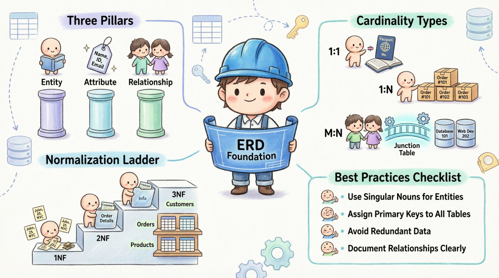
To understand the logic, we must dissect the anatomy of the diagram. Every ERD is built upon three pillars:
Entities: These represent the nouns of your system. In a library system, these might be Book, Author, and Member. In a database, these translate directly to tables.
Attributes: These are the properties describing the entities. For a Book, attributes include Title, ISBN, and Publication Date. These become the columns in your tables.
Relationships: These define how entities interact. This is where the logic lives. It specifies the cardinality and the constraints of the connection.
⚙️ The Logic of Cardinality
Cardinality is the most misunderstood concept in database design. It is not just about numbers; it is about rules. 📏 It answers the question: “How many instances of one entity relate to instances of another?”
There are three primary types of relationships that define the structure of your data:
1. One-to-One (1:1)
This relationship occurs when one instance of an entity is associated with exactly one instance of another entity. This is rare but exists for specific logical needs.
Example: A Person and a Passport. One person has one passport. One passport belongs to one person.
Implementation Logic: You often merge these into a single table or use a foreign key in one table referencing the primary key of the other.
2. One-to-Many (1:N)
This is the most common relationship in data modeling. One entity can relate to many instances of another, but the reverse is not true.
Example: A Customer and an Order. One customer can place many orders. However, a single order belongs to only one customer.
Implementation Logic: The foreign key is placed on the “many” side (the Order table) to reference the “one” side (the Customer table).
3. Many-to-Many (M:N)
This relationship indicates that instances of one entity can relate to multiple instances of another, and vice versa.
Example: Students and Courses. A student can enroll in many courses. A course can have many students.
Implementation Logic: This cannot be implemented directly in a relational database. It requires a junction table (or associative entity) to break the relationship into two one-to-many relationships.
Relationship Type | Logical Description | Database Implementation | Example Scenario |
|---|---|---|---|
One-to-One (1:1) | Single instance links to single instance | Foreign Key on either side | Employee ↔ Office Assignment |
One-to-Many (1:N) | One instance links to multiple instances | Foreign Key on the “Many” side | Department ↔ Employees |
Many-to-Many (M:N) | Multiple instances link to multiple instances | Junction/Associative Table Required | Teacher ↔ Subjects |
🔗 Understanding Relationships and Constraints
Relationships are not just lines on a diagram; they represent business rules. If you violate these rules in your design, your data becomes unreliable. This is where the concept of cardinality constraints comes into play.
Participation Constraints
These define whether an entity is required to participate in a relationship. This is often visualized with double lines in diagrams.
Total Participation: Every instance of Entity A must relate to an instance of Entity B. (e.g., Every Order must have a Customer).
Partial Participation: An instance of Entity A may or may not relate to Entity B. (e.g., A Customer may or may not have a Credit Card).
Referential Integrity
The ERD enforces referential integrity. This ensures that you cannot create an order for a customer that does not exist. The foreign key constraint acts as a gatekeeper, preventing orphaned records. This logic is crucial for maintaining data consistency over time.
🧱 Normalization and the ERD
Designing an ERD is not complete without considering normalization. Normalization is the process of organizing data to reduce redundancy and improve integrity. The ERD is the visual tool used to achieve these normal forms.
First Normal Form (1NF)
The first rule is atomicity. Each column must contain only a single value. Your ERD should not show a column for “Phone Numbers” that lists three numbers in one cell. Instead, the relationship should be split, or the data structure must change to accommodate multiple entries.
Second Normal Form (2NF)
2NF builds on 1NF by ensuring that all non-key attributes are fully dependent on the primary key. If you have a table where some data depends on a part of a composite key, you must split the table. The ERD helps visualize this by showing which attributes belong to which entity.
Third Normal Form (3NF)
3NF eliminates transitive dependencies. If a non-key attribute depends on another non-key attribute, it violates this form. For example, if a City depends on a Zip Code, and the Zip Code depends on the Address, you should separate the City information into its own entity or table.
Why this matters: If you skip normalization, your ERD will look simple, but your database will be messy. Updates become difficult. Deleting records can accidentally remove necessary data. The logic of the ERD protects you from these structural flaws.
🚫 Common Design Mistakes
Even experienced designers fall into traps. Identifying these pitfalls early saves months of refactoring.
1. Ignoring the Many-to-Many Reality
Attempting to force a many-to-many relationship directly into a single table is a logical fallacy. This leads to duplicate data and ambiguity. Always use an associative entity for M:N relationships.
2. Over-Normalization
While normalization is good, too much of it fragments data too aggressively. This can lead to complex joins that degrade query performance. The ERD must balance logical purity with physical performance.
3. Ambiguous Naming Conventions
Names like Table1 or Field1 provide no context. An ERD relies on clear naming to communicate logic. Use descriptive names that reflect the business domain.
4. Missing Attributes
Designers often focus on relationships and forget attributes. A table without attributes is just a container. Ensure every entity has the necessary data points to function independently.
✅ Best Practices for Effective ERDs
To create a diagram that serves as a reliable guide, follow these structured practices.
Start with the Entities: Identify the core objects of your system first. Do not get bogged down in relationships until you know what exists.
Define Primary Keys Explicitly: Every table needs a unique identifier. Mark these clearly. This anchors the relationship logic.
Use Standard Notation: Whether you use Crow’s Foot notation or Chen notation, consistency is key. It reduces cognitive load for anyone reading the diagram later.
Iterate the Design: An ERD is rarely perfect on the first draft. Review it against business requirements. Ask questions like, “Can a user exist without an address?” and adjust accordingly.
Document the Logic: Add notes to the diagram explaining complex rules. A line between tables tells you what is connected, but a note tells you why.
🔄 From Logic to Implementation
Once the ERD is finalized, it becomes the source of truth for the physical schema. The transition from diagram to database is where the logic is codified.
Logical to Physical: The ERD is logical. It describes concepts. The physical schema describes storage. The ERD must be translated into specific data types (e.g., Integer, Varchar, Date) suitable for the target system.
Constraints as Code: The relationships drawn in the ERD become Foreign Key Constraints in the database definition. The cardinality becomes check constraints or unique indexes.
Validation: Use the ERD to validate the generated schema. Does every table exist? Are all relationships preserved? Is the data integrity maintained?
🛠️ The Impact on Maintenance
A well-structured ERD pays dividends during the maintenance phase. When requirements change, the diagram shows the ripple effects.
Impact Analysis: If you need to add a new field to an entity, the ERD shows which tables are affected by that change.
Refactoring: If the database becomes slow, the ERD helps identify inefficient joins or missing indexes based on the relationship paths.
Documentation: The ERD serves as living documentation. New team members can understand the system architecture by studying the diagram.
📝 Summary of Key Concepts
To recap, the logic behind ERDs is about clarity, integrity, and structure. Here are the essential takeaways for your design process:
Entities represent the core objects.
Attributes define the properties of those objects.
Relationships define the connections and rules between objects.
Cardinality determines the volume of those connections (1:1, 1:N, M:N).
Normalization ensures data is organized to prevent redundancy.
Constraints enforce the business rules defined in the diagram.
By treating the Entity-Relationship Diagram as the starting point of your database design, you ensure that the system is built on a foundation of logic rather than assumption. This approach reduces technical debt and creates a scalable architecture. Take the time to draw the lines correctly. The data inside will thank you. 🚀