


Understanding the structure of a software system requires more than just knowing the classes involved. It demands a clear picture of how those classes interact at a specific moment in time. This is where the object diagram becomes an essential tool for system architects and developers. While class diagrams define the blueprint, object diagrams capture the snapshot. They provide a static view of instances, their attributes, and the links connecting them.
In this guide, we explore the mechanics of object diagrams in detail. We examine how they function within dynamic systems, why they are critical for debugging and documentation, and how to construct them effectively without relying on specific commercial tools. By the end, you will understand how to leverage these diagrams to clarify complex relationships and ensure system integrity.
Understanding Object Diagrams 📋
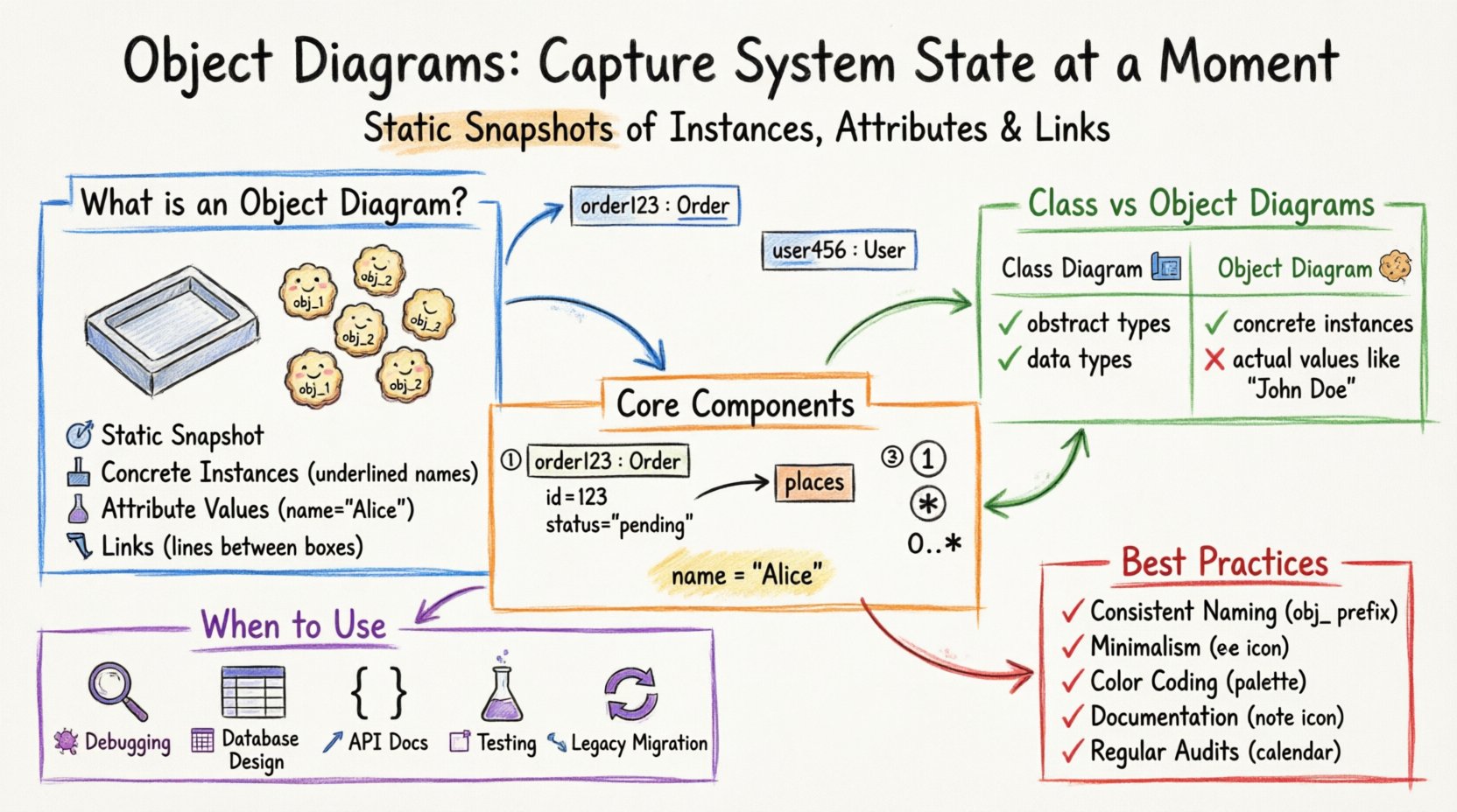
An object diagram is a structural diagram that illustrates a specific instance of a system at a given point in time. It represents the concrete realization of the abstract patterns defined in a class diagram. Think of a class diagram as a cookie cutter and the object diagram as the cookies themselves. The shape is defined by the cutter, but the cookies are the actual instances with specific properties.
These diagrams are particularly valuable when dealing with complex associations. When a system involves multiple levels of inheritance or polymorphism, a class diagram might become cluttered. An object diagram simplifies this by showing the actual data flowing through the system. It answers the question: What does the data look like right now?
Key Characteristics
- Static Snapshot: Unlike sequence diagrams which show behavior over time, object diagrams show state at a single instant.
- Concrete Instances: Objects are named with an underline prefix, distinguishing them from class names.
- Attribute Values: Unlike class diagrams that list types, object diagrams often list actual values.
- Links: Associations between objects are explicitly drawn as lines connecting the instances.
Object Diagrams vs. Class Diagrams 🆚
Confusion often arises between class diagrams and object diagrams because they share similar visual syntax. However, their purpose and scope differ significantly. A class diagram defines the types; an object diagram defines the data.
| Feature | Class Diagram | Object Diagram |
|---|---|---|
| Representation | Abstract types (Blueprints) | Concrete instances (Data) |
| Object Name | Class Name (e.g., Customer) | Instance Name (e.g., customer1: Customer) |
| Attribute Display | Data Types (e.g., String) | Actual Values (e.g., “John Doe”) |
| Time Context | Always valid (Structural) | Specific Moment (State) |
| Use Case | System Design | Debugging & Testing |
When analyzing a database schema, the table structure resembles a class diagram. The rows in the table represent object diagrams. Understanding this distinction helps in mapping database records to visual models accurately.
Core Components of an Object Diagram 🧩
To build a meaningful object diagram, you must understand the specific elements that constitute it. Each element serves a purpose in defining the state of the system.
1. Object Instances
Instances are the primary building blocks. They are rendered as rectangles divided into two sections. The top section contains the object name followed by a colon and the class name. The bottom section lists the attribute values.
- Name Format: objectName : ClassName
- Example: order123 : Order
- Visibility: Access modifiers (+, -, #) can be shown, though often omitted for simplicity in snapshots.
2. Links
Links represent associations between object instances. While class diagrams show associations between types, object diagrams show connections between specific instances.
- Association Line: A straight line connecting two object rectangles.
- Role Names: Labels on the line indicating the relationship from one object to another (e.g., places, owns).
- Navigability: Arrows indicate the direction of knowledge or access between instances.
3. Multiplicity
Multiplicity constraints apply to object diagrams just as they do to class diagrams. They define how many instances can be linked.
- One-to-One: A single link connects exactly one instance to another.
- One-to-Many: One instance links to multiple others.
- Zero-to-Many: An instance may have no links or multiple links.
4. Attribute Values
This is the differentiator. Instead of showing String name, an object diagram shows name = “Alice”. This level of detail is crucial for validating logic during the testing phase.
When to Deploy Object Diagrams 🛠️
Not every project requires object diagrams. They add value when the system complexity makes abstract class structures insufficient for understanding the data flow. Here are specific scenarios where they are most effective.
- Debugging Complex Logic: When a bug occurs, an object diagram can show the exact state of variables that led to the error. It captures the “before” and “after” states of a function execution.
- Database Schema Design: Before writing SQL queries, visualizing the data instances helps ensure referential integrity and proper normalization.
- API Documentation: Showing example JSON payloads is essentially creating an object diagram for the API response structure.
- Testing Scenarios: Test cases often require specific data states. Object diagrams define these preconditions clearly.
- Legacy System Migration: When modernizing old systems, object diagrams help map existing data structures to new class models.
Step-by-Step Construction Process 📝
Creating an object diagram requires a systematic approach. Follow these steps to ensure accuracy and clarity.
- Identify the Scope: Determine which part of the system you are visualizing. Do not attempt to diagram the entire enterprise at once. Focus on a single use case or transaction.
- Select Relevant Classes: Choose the classes involved in this specific scenario. Ignore unrelated classes to reduce noise.
- Create Instances: Instantiate the selected classes. Assign unique names to each instance.
- Define Attribute Values: Populate the attributes with realistic sample data. Use types that match the expected domain values.
- Draw Links: Connect the instances according to the associations defined in the class diagram. Ensure multiplicity constraints are respected.
- Review Relationships: Check for orphaned objects or links that violate business rules.
Navigating Relationships and Links 🔗
The integrity of an object diagram relies heavily on how relationships are depicted. Misunderstanding these links can lead to architectural flaws.
Association Links
These represent the most basic connection. If an Order is linked to a Customer, the link represents the fact that this specific order belongs to this specific customer.
Aggregation vs. Composition
Distinguishing between these two is vital for memory management and lifecycle management.
- Aggregation: The whole can exist without the part. If the Department object is deleted, the Employee objects might still exist in the system.
- Composition: The part cannot exist without the whole. If the House object is deleted, the Room objects cease to exist.
Object diagrams should visually represent this distinction, often using diamond symbols or specific line styles if supported by the modeling environment.
Common Challenges and Solutions ⚠️
Even experienced architects face hurdles when modeling object states. Recognizing these pitfalls early saves time.
- Overcrowding: Trying to show every instance in a large system makes the diagram unreadable.
Solution: Use a subset approach. Show the most critical paths or a representative sample. - Versioning Issues: As the system evolves, old object diagrams become obsolete.
Solution: Treat these diagrams as living documents. Archive old versions and create new ones when major changes occur. - Confusion with State Diagrams: Confusing the state of an object with the state machine of an object.
Solution: Remember: Object diagrams show data values. State diagrams show behavior transitions. - Missing Values: Leaving attributes blank can imply null, but it often just means unknown.
Solution: Use standard notations for null values to avoid ambiguity.
Integrating with Other UML Models 🔄
An object diagram does not exist in isolation. It complements other modeling artifacts to provide a holistic view of the system.
With Class Diagrams
The class diagram provides the rules; the object diagram provides the evidence. If an object diagram shows a link that violates a class diagram constraint, the class diagram needs updating.
With Sequence Diagrams
Sequence diagrams show the flow of messages over time. Object diagrams show the state before and after those messages. Using both allows you to trace the impact of a message on the data structure.
With State Diagrams
State diagrams define the lifecycle of a single object. Object diagrams show the collection of objects and their relationships. Together, they define both the behavior and the structure of the system.
Best Practices for Maintenance 📚
To keep your modeling efforts effective, adhere to these guidelines.
- Consistent Naming: Use a standard convention for object names. Prefixes like obj_ or inst_ can help distinguish them from class names.
- Minimalism: Only include attributes that are relevant to the current context. Reducing visual clutter improves comprehension.
- Color Coding: Use color to indicate status. For example, green for valid states, red for error states, or gray for inactive objects.
- Documentation: Add notes to explain complex links or unusual data values. Text annotations prevent misinterpretation.
- Regular Audits: Periodically review diagrams against the actual codebase. Stale diagrams are worse than no diagrams.
The Future of Static Modeling 🚀
As software systems become more distributed and cloud-native, the role of static modeling evolves. Microservices architecture introduces new challenges in tracking object states across boundaries. Object diagrams help visualize these distributed states.
Integration with automated testing tools is also growing. Some modeling environments can generate test fixtures directly from object diagrams. This bridges the gap between design and implementation, ensuring that the code matches the visual plan.
Furthermore, static analysis tools use these diagrams to detect potential runtime errors. By analyzing the links and multiplicities, tools can predict null pointer exceptions or memory leaks before the code is even compiled.
Summary of Key Takeaways 📌
- Object diagrams provide a concrete view of system instances at a specific time.
- They complement class diagrams by showing actual data rather than abstract types.
- Links represent associations between specific instances, respecting multiplicity.
- They are essential for debugging, testing, and documenting complex data flows.
- Maintain them regularly to ensure they reflect the current system state.
Mastering the art of object modeling requires patience and attention to detail. It is not about creating pretty pictures; it is about communicating complex data relationships clearly. By adhering to these principles, you ensure that your system designs remain robust and understandable throughout the development lifecycle.
Start applying these techniques to your current projects. Identify a complex module, sketch its object state, and observe how it clarifies your understanding of the underlying data. You will find that the effort invested in visualization pays dividends in code quality and reduced debugging time.