Welcome to this detailed reference for the ArchiMate modeling language. This guide provides a structured overview of the syntax, notation, and core elements used within the framework. Whether you are documenting business processes or mapping technology infrastructure, understanding the visual language is essential for effective communication. We will explore the layers, domains, and relationships that define the architecture without relying on specific software tools.
🏛️ Foundational Concepts
ArchiMate is designed to represent enterprise architecture. It provides a standardized way to describe, analyze, and visualize the relationships between business, application, and technology layers. The syntax ensures that all stakeholders, from business managers to technical engineers, share a common understanding of the system structure.
The notation is built on a few core principles:
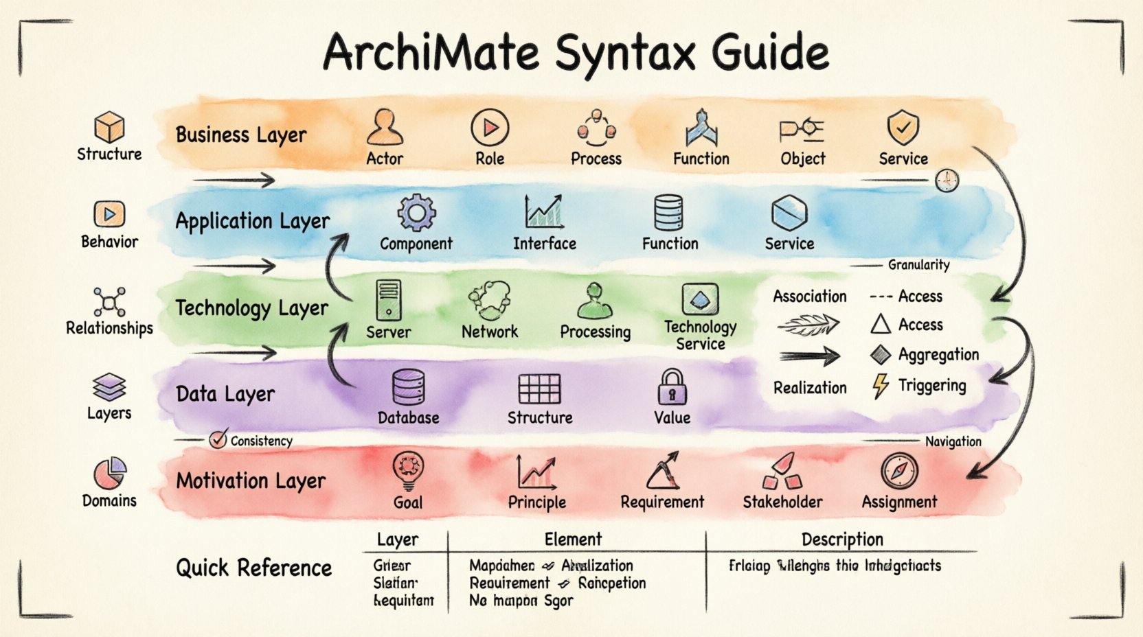
- Structure: Elements represent static aspects of the architecture.
- Behavior: Elements represent dynamic aspects, such as processes or functions.
- Relationships: Arrows and lines connect elements to show how they interact.
- Layers: Different levels of abstraction are organized vertically.
- Domains: Specific areas of focus, such as motivation or strategy.
Using this standardized syntax allows architects to create diagrams that are consistent across different projects. It reduces ambiguity and ensures that the model remains readable over time.
🧩 The ArchiMate Layers
The architecture is divided into horizontal layers. Each layer represents a specific aspect of the enterprise. Moving from top to bottom, the layers generally shift from abstract business concepts to concrete physical implementations.
1. Business Layer
This layer focuses on the business side of the enterprise. It describes how the organization operates, what it does, and who is involved.
- Business Actor: A human or organization performing a role.
- Business Role: A set of responsibilities within the business.
- Business Process: A structured set of activities.
- Business Function: A capability to perform a set of activities.
- Business Object: A piece of information used in the business.
- Business Service: A unit of functionality offered to a stakeholder.
2. Application Layer
The application layer sits below the business layer. It represents the software systems that support business processes.
- Application Component: A modular part of an application system.
- Application Interface: A point of interaction with an application.
- Application Function: A function implemented by an application.
- Application Service: A unit of functionality provided by an application.
- Application Interface: A point of interaction between components.
3. Technology Layer
The technology layer represents the hardware and network infrastructure required to run the applications.
- Device: A computational device.
- System Software: Software that manages hardware resources.
- Network: A communication network.
- Processing Structure: A set of processes running on a device.
- Technology Service: A unit of functionality provided by the technology.
4. Data Layer
While often integrated with the Business or Application layers, the Data Layer focuses specifically on the storage and flow of information.
- Data Object: A conceptual representation of data.
- Data Structure: The organization of data attributes.
- Data Value: A specific value of a data attribute.
5. Motivation Layer
This layer explains the “why” behind the architecture. It connects the structural elements to the drivers and goals.
- Goal: Something an actor wants to achieve.
- Principle: A rule to guide decision making.
- Requirement: A condition or capability that must be met.
- Stakeholder: A person or organization with an interest in the architecture.
- Assignment: Assigns a role to an actor or a function to an agent.
🔗 Understanding Relationships
Relationships define how elements interact. They are crucial for showing flow, dependency, and access. Using the correct relationship syntax prevents misinterpretation of the model.
Association
Association is a general relationship indicating that two elements are connected in some way. It is often used for static relationships.
- Used between Business Objects and Business Processes.
- Indicates a structural link rather than a flow.
Flow
Flow represents the movement of information or materials between elements. It is dynamic in nature.
- Typically connects Business Processes to Business Objects.
- Shows the input and output of data.
Access
Access indicates that one element uses or accesses another element. It is commonly used between Applications and Functions.
- Shows usage relationships.
- Can apply to data or services.
Aggregation
Aggregation represents a “whole-part” relationship. One element is composed of other elements.
- Used to break down complex functions into smaller components.
- Shows hierarchical structures.
Realization
Realization indicates that one element implements or specifies another. It is often used to show how a service is realized by a function.
- Connects Business Services to Application Services.
- Connects Application Services to Application Functions.
Triggering
Triggering shows that the occurrence of one event causes another event. It is specific to process flows.
- Connects Business Processes.
- Indicates sequence and causality.
📊 Element Summary Table
The following table summarizes the core elements across the primary layers for quick reference.
| Layer | Element Type | Description |
|---|---|---|
| Business | Business Process | A structured set of activities |
| Business | Business Service | Functionality offered to stakeholders |
| Application | Application Component | Modular part of an application |
| Application | Application Interface | Point of interaction |
| Technology | Device | Computational device |
| Technology | Network | Communication network |
| Motivation | Goal | Desired outcome |
| Motivation | Requirement | Condition to be met |
🌐 Domains and Context
In addition to layers, ArchiMate defines domains. These domains group elements by their nature. Understanding the domain helps in organizing the model logically.
- Business Domain: Focuses on business capabilities, processes, and roles.
- Application Domain: Focuses on software systems and their interactions.
- Technology Domain: Focuses on infrastructure and hardware.
- Strategy Domain: Focuses on goals, principles, and requirements.
Each domain can be modeled independently or in conjunction with others. This modularity allows architects to zoom in on specific areas without losing the broader context.
🧱 Implementation Considerations
When creating models, consistency is key. Using the correct notation ensures that the diagrams remain valid over time. Here are some considerations for implementation.
Consistency
Ensure that naming conventions are consistent across the model. Use standard terms for elements to avoid confusion. For example, always refer to “Business Process” rather than just “Process”.
Granularity
Decide on the level of detail required for the model. Too much detail can make the diagram cluttered. Too little detail can make it useless. Aim for a balance that serves the specific purpose of the diagram.
Navigation
Design the model so that it is easy to navigate. Use sub-models to break down complex areas. This keeps the main view clean while allowing access to detailed information when needed.
🚦 Common Modeling Patterns
Certain patterns emerge frequently in enterprise architecture. Recognizing these patterns can speed up the modeling process.
- Service Layering: Showing how business services are supported by application services, which in turn run on technology services.
- Data Flow: Illustrating how data moves from a source system to a destination system through a process.
- Role Assignment: Mapping actors to roles to show responsibility distribution.
- Goal Decomposition: Breaking down high-level goals into sub-goals and requirements.
🛠️ Best Practices for Clarity
Clear communication is the goal of any architecture model. Following best practices helps achieve this.
- Limit Connections: Avoid crossing lines. Arrange elements to minimize intersections.
- Use White Space: Leave empty space around elements to improve readability.
- Color Coding: While CSS is not used here, logical grouping can be achieved through layout and hierarchy.
- Label Relationships: Always label arrows to indicate the type of relationship clearly.
- Review Regularly: Models drift over time. Regular reviews ensure they match the current state of the enterprise.
🔍 Detailed Element Behaviors
Understanding the behavior of elements is as important as knowing their syntax. Some elements represent static structures, while others represent dynamic actions.
Static Elements
These elements describe the state of the system at a point in time.
- Business Object: Represents information. It does not move but is acted upon.
- Device: Represents hardware. It provides the platform for execution.
- Business Role: Represents a position. It defines the responsibility.
Dynamic Elements
These elements describe actions and changes.
- Business Process: Represents a flow of activities. It changes the state of objects.
- Application Function: Represents a calculation or operation. It transforms data.
- Event: Represents a situation or occurrence. It triggers behavior.
🔄 Inter-Layer Relationships
One of the most powerful aspects of ArchiMate is the ability to connect elements across layers. This ensures traceability from business goals down to physical devices.
- Business to Application: A business service is realized by an application service.
- Application to Technology: An application function is realized by a technology service.
- Business to Technology: A business process is supported by a device.
These cross-layer connections are vital for impact analysis. If a technology device fails, you can trace the impact up to the business service affected.
📝 Syntax Rules and Conventions
To maintain validity, specific syntax rules must be followed.
- Shape Consistency: Each element type has a specific shape. Do not mix shapes.
- Arrow Direction: Arrows indicate direction of flow or dependency. Ensure they point in the correct logical direction.
- Line Styles: Solid lines typically indicate relationships. Dashed lines might indicate realization or assignment depending on the specific notation version.
- Text Labels: Keep labels concise. Use full names in the legend if space is limited in the diagram.
🧭 Conclusion on Usage
Mastering the syntax of ArchiMate requires practice and attention to detail. The goal is to create models that are accurate, consistent, and useful. By adhering to the layer structure, understanding the relationships, and following best practices, architects can build robust representations of complex enterprise systems. This reference serves as a foundation for developing those skills further.