Object diagrams are a critical component of Unified Modeling Language (UML) documentation. They provide a static snapshot of a system at a specific point in time. Unlike class diagrams, which define the blueprint, object diagrams depict actual instances. Many students struggle to distinguish between the theoretical structure and the practical implementation. This often leads to diagrams that are confusing, inaccurate, or misleading. Understanding the common errors is essential for creating clear system models. This guide outlines the frequent pitfalls and offers corrections based on standard modeling conventions.
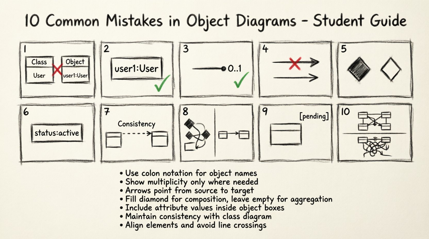
1. Confusing Class Definitions with Instances 🧠
The most fundamental error occurs when students treat object diagrams exactly like class diagrams. A class diagram defines types, attributes, and operations. An object diagram defines specific instances of those types. If you draw a class box, you are defining a type. If you draw an object box, you are defining a concrete entity. Mixing these up creates ambiguity about whether you are describing the potential or the actual.
- The Error: Labeling an object box with just a type name without an instance identifier.
- The Correction: Every object must have a unique identifier, typically written as instanceName : ClassName.
- The Impact: Without clear distinction, reviewers cannot determine if the diagram represents a single configuration or the general structure of the software.
When creating an object, you are showing a specific moment in the system’s lifecycle. For example, if you have a class User, the object diagram should show user1 : User, not just User. This distinction ensures that the model reflects reality rather than theory.
2. Incorrect Instance Naming Conventions 🏷️
Naming objects is not merely about labeling; it is about identification. In many modeling standards, an object name consists of an optional instance name followed by a colon and the class name. Students often omit the instance name entirely, resulting in generic labels like Customer instead of customer01 : Customer.
- The Error: Using only the class name for the object label.
- The Correction: Always prefix the class name with a unique identifier if multiple instances of the same class exist.
- The Impact: It becomes impossible to trace specific data flows or track state changes for individual entities.
Consider a scenario where you have multiple bank accounts. If you label them both simply Account, you cannot distinguish between Account1 and Account2 in your analysis. Consistent naming allows for precise referencing in subsequent documentation or code generation.
3. Misinterpreting Multiplicity and Cardinality 🔢
Multiplicity defines how many instances of one class relate to one instance of another. This is often represented as a range, such as 0..1, 1, or 0..*. Students frequently misplace these numbers or apply them incorrectly to object diagrams where they belong on class diagrams.
- The Error: Drawing relationships without multiplicity indicators or using class-level multiplicity on specific object links.
- The Correction: Ensure the object diagram reflects the constraints defined in the class diagram. If a class diagram says
1, the object link must show that one specific relationship exists. - The Impact: Ambiguity regarding data integrity and relationship constraints.
Multiplicity is a constraint on the relationship. If a Manager class has a relationship with Employee marked as 1, an object diagram showing manager1 linked to employee1 and employee2 violates that constraint unless the multiplicity allows for multiple employees. Students often overlook the numerical constraints at the ends of the association lines.
4. Ignoring Link Directionality and Navigability ➡️
Relationships in object diagrams are not always bidirectional. Navigability indicates which direction the relationship can be traversed. A student might draw a line between two objects but fail to indicate which end initiates the connection.
- The Error: Drawing plain lines without arrowheads on association links.
- The Correction: Use open arrowheads to show navigability. If
Object Aknows aboutObject B, the arrow points from A to B. - The Impact: Reviewers cannot determine how data is accessed or how objects find each other in memory.
In a system where a Order references a Customer, the order holds the reference. The arrow should point from Order to Customer. This indicates that to find the customer, you start at the order. Reversing this implies the customer holds the reference to the order, which may be a logical error in the design.
5. Confusing Aggregation with Composition 🧩
Composite relationships define a strong “part-of” bond where the lifecycle of the part depends on the whole. Aggregation implies a weaker relationship where parts can exist independently. Students often use the same line style for both, or use them interchangeably.
- The Error: Treating all containment relationships as simple associations.
- The Correction: Use the filled diamond for Composition and the empty diamond for Aggregation.
- The Impact: Misunderstanding of object lifecycle management and memory allocation.
If a Car contains an Engine, the engine usually cannot exist without the car in this context (Composition). If a Department contains Employees, the employee might exist even if the department dissolves (Aggregation). Mixing these up suggests incorrect architectural decisions regarding resource ownership.
6. Omitting Attribute Values for Instances 📝
One of the primary purposes of an object diagram is to show state. A class diagram defines what attributes exist. An object diagram should show what values those attributes hold at a specific moment. Students often draw the object box but leave the attribute section empty.
- The Error: Showing the object shape but no data inside the attribute compartment.
- The Correction: Populate the attribute section with current values (e.g.,
status: active). - The Impact: The diagram loses its value as a test case or a debugging snapshot.
Imagine debugging a system failure. A class diagram tells you the structure. An object diagram tells you the state. If you have an object transaction1 : Transaction, you should see amount: 100.00 and date: 2023-10-01. Without these values, the diagram is just a schematic, not a snapshot of reality.
7. Inconsistency with the Class Diagram 🔄
The object diagram is derived from the class diagram. It cannot contradict the structure defined at the higher level. A common mistake is adding attributes, operations, or relationships to an object diagram that do not exist in the corresponding class diagram.
- The Error: Adding a new relationship line to an object that wasn’t defined in the class.
- The Correction: Cross-reference every link in the object diagram with the class diagram definition.
- The Impact: Confusion regarding the scope of the system and invalid data models.
If the class diagram does not define a relationship between Product and Review, the object diagram cannot show an instance of Product linked to an instance of Review. This breaks the logical contract of the model. Consistency ensures that the implementation can actually be built according to the design.
8. Overcrowding the Snapshot 📉
Students often feel compelled to show every single object in a system on one diagram. This leads to cluttered, unreadable visuals. An object diagram is meant to illustrate a specific scenario or state, not the entire database.
- The Error: Including hundreds of instances in a single view.
- The Correction: Limit the diagram to the relevant objects for the specific use case being modeled.
- The Impact: Loss of clarity and inability to see the critical relationships.
If you are modeling a login process, you do not need to show the Order objects or the Inventory objects unless they are directly involved. Focus on the User, Session, and Authenticator. Keeping the scope narrow makes the diagram a useful tool for communication rather than a wall of text.
9. Ignoring Lifecycle States ⏳
Objects are not static; they move through states. While state diagrams cover this explicitly, object diagrams can hint at lifecycle status. Students often ignore the state of the object when creating the instance.
- The Error: Treating all objects as fully initialized and active.
- The Correction: Indicate states where relevant (e.g.,
order1 : Order[pending]). - The Impact: Failure to capture transient states that are crucial for system logic.
Some modeling tools allow you to denote the state of an object directly in the diagram. If an object is in a “Created” state versus a “Deleted” state, it affects how the system handles it. Ignoring this nuance can lead to logic errors where the system attempts to process a non-existent or finalized object.
10. Poor Visual Layout and Spacing 📐
A diagram is a communication tool. If it is visually chaotic, the information is lost. Students often place objects randomly without regard for grouping or alignment. This makes tracing connections difficult.
- The Error: Random placement of boxes with crossing lines and no grouping.
- The Correction: Group related objects logically. Use alignment and spacing to create visual hierarchy.
- The Impact: Increased cognitive load for the reader and potential misinterpretation of connections.
Organize the diagram so that the flow of data is visually apparent. If Object A connects to Object B, place them close enough to minimize line length. Avoid lines crossing other boxes unless necessary. A clean layout signals a clean design.
Summary of Common Errors Table 📊
| Mistake Category | Typical Error | Correct Approach |
|---|---|---|
| Identification | Missing instance name | Use name : Class format |
| Relationships | Missing multiplicity | Adhere to class diagram constraints |
| Navigability | Undirected lines | Use arrowheads for flow |
| Data | No attribute values | Show specific instance data |
| Consistency | New relationships | Match class diagram structure |
| Scope | Too many objects | Focus on relevant subset |
| Visuals | Crossing lines | Align and group logically |
Deep Dive: Relationship Semantics 🧠
Understanding the semantic meaning of relationships is crucial. A simple line does not convey enough information. Students often assume that a line implies a direct database foreign key. While often true, it is not a rule. The relationship represents a logical connection.
Consider a Library system. A Book might be associated with a Genre. If the class diagram shows a many-to-many relationship, the object diagram should reflect that a specific book instance is linked to a specific genre instance. However, if the system implementation uses a join table, the object diagram might still show a direct link depending on the abstraction level. The key is consistency with the design intent, not necessarily the physical implementation.
Students frequently forget to label the relationship ends with role names. If a User has a relationship with Order, the role on the User end might be “places” and the role on the Order end might be “placedBy”. Omitting these names makes the diagram harder to read. Always include role names where they add clarity.
Best Practices Checklist ✅
To ensure your object diagrams are accurate and useful, follow this checklist before finalizing your work.
- Verify Naming: Does every object have an instance name?
- Check Multiplicity: Do the links match the class diagram constraints?
- Validate Values: Are attribute values realistic for the scenario?
- Review Links: Do all arrows point in the correct direction?
- Check Consistency: Do all relationships exist in the class diagram?
- Assess Clarity: Is the layout easy to follow without crossing lines?
- Limit Scope: Are only necessary objects included?
- Label Roles: Are relationship roles named where helpful?
Adhering to these standards reduces the cognitive load on anyone reading your documentation. It also minimizes the risk of miscommunication during the development phase. A well-constructed object diagram serves as a bridge between design and code.
Final Thoughts on Modeling Accuracy 🎯
Accuracy in modeling is not about perfection; it is about clarity and intent. When you avoid these common mistakes, you create diagrams that truly serve their purpose. They become tools for analysis rather than just artifacts for compliance. Remember that an object diagram is a representation of a moment in time. It captures a state that the system passes through. By treating it with the rigor of a class diagram, you ensure that the model remains a reliable source of truth throughout the software development lifecycle.
Take the time to review your work against the checklist. Ensure that every line has meaning and every label is precise. This attention to detail distinguishes a novice modeler from a skilled architect. Focus on the relationships and the data, and the structure will follow naturally.
Conclusion 🏁
Creating object diagrams requires precision and a deep understanding of system states. By avoiding the pitfalls outlined in this guide, you ensure that your models are clear, accurate, and useful. Focus on the relationship between the class definitions and the instance data. Maintain consistency across your documentation. With practice, these errors become less frequent, and your diagrams become more effective communication tools.