In the landscape of software architecture and system modeling, few concepts bridge the gap between abstract design and concrete reality as effectively as object instantiation. While class diagrams define the blueprint of a system, object diagrams provide a snapshot of the system in action at a specific moment in time. At the heart of this snapshot lies the process of object instantiation. This guide explores the mechanics, syntax, and significance of instantiation within the context of Unified Modeling Language (UML) object diagrams.
Understanding how individual objects are created from classes is fundamental for anyone tasked with visualizing system state, debugging complex interactions, or documenting specific scenarios. This is not merely about drawing boxes; it is about representing the actual data flow and structural dependencies that exist during runtime.
🔍 What is Object Instantiation?
Object instantiation is the process of creating a specific instance of a class. In programming terms, if a class is a cookie cutter, the instantiated object is the actual cookie produced. In the context of modeling, this distinction is vital. A class diagram describes what exists (the structure), while an object diagram describes who exists (the state).
When we instantiate an object, we are defining:
- A unique identifier: Each object must be distinguishable from others, even if they belong to the same class.
- A specific state: Attributes hold concrete values rather than abstract data types.
- A relationship to other objects: Instantiated objects connect to other instances via links.
Without instantiation, a model remains theoretical. Instantiation grounds the model in a specific scenario, making it possible to analyze behavior, validate constraints, and verify structural integrity before code is written.
🏗️ Syntax and Naming Conventions
Visualizing an instantiated object requires adherence to specific notation rules. Unlike a class, which is typically represented by a rectangle with the class name in bold, an object has a distinct appearance to denote its instance status. The standard notation for an object instance includes the object name followed by a colon and the class name.
🏷️ Object Naming Rules
The name of an object instance often follows a convention to ensure clarity within the diagram. Common practices include:
- Lowercase first letter: Object names often start with a lowercase letter to differentiate them from class names, which usually start with an uppercase letter. For example,
customer1vsCustomer. - Uniqueness: Within the context of a single diagram, every object instance must have a unique name. You cannot have two objects named
order1in the same diagram unless they represent the same specific entity. - Explicit Type Declaration: The type is always explicitly stated after the colon. This reinforces the relationship between the instance and its class definition.
Consider the following notation example:
order1 : Order
This notation explicitly tells the viewer that order1 is a specific instance of the Order class. It distinguishes this entity from the general concept of an order.
📝 Including Attribute Values
One of the most powerful features of object diagrams is the ability to show attribute values. While class diagrams list attribute types (e.g., price : float), object diagrams can list attribute values (e.g., price = 99.99). This level of detail is crucial for debugging and scenario analysis.
When displaying attribute values in an object diagram, follow these guidelines:
- Literal Values: Use the actual value assigned to the attribute. If an attribute represents a string, enclose it in quotes.
- Null Values: Indicate when an attribute has no value, often represented as
nullorNone. - Collection Values: If an attribute holds a list or array, show the contents or a representative subset.
Example of an object with state:
invoice1 : Invoice {
  number = "INV-2023-001"
  total = 1500.00
  status = "Paid"
}
This notation allows stakeholders to see exactly what the system looks like when an invoice is paid, rather than just knowing that an invoice can be paid.
🔗 Relationships and Links
Objects do not exist in isolation. They interact with other objects through associations, aggregations, and compositions. In object diagrams, these relationships are visualized as links.
🔗 Representing Links
A link is a specific instance of an association. If an association defines the structural path between two classes (e.g., Customer and Order), a link defines a specific path between two instances (e.g., customer1 and order1).
When drawing links in an object diagram:
- Connect Instances: Draw a line between the boxes representing the objects.
- Label the Link: Similar to associations, links can be labeled to describe the nature of the connection.
- Indicate Role Names: If the association has roles (e.g.,
buyerandseller), the link should reflect these roles.
📊 Multiplicity in Object Diagrams
Multiplicity constraints defined in the class diagram (e.g., one-to-many) must be respected in the object diagram. However, the object diagram shows a specific realization of that constraint.
For example, if a Customer can place many Orders, the object diagram might show customer1 linked to order1, order2, and order3. This visualizes the specific cardinality for that moment in time.
Key considerations for links include:
- Directionality: Links are often bidirectional, but the navigation direction matters for the logic being modeled.
- Cardinality: Ensure the number of links matches the multiplicity defined in the class model.
- Aggregation vs. Composition: Distinguish between shared ownership (aggregation) and exclusive ownership (composition) when drawing links.
⚖️ Object Diagrams vs. Class Diagrams
It is common to confuse object diagrams with class diagrams. While both belong to the structural category of UML, they serve different purposes. A class diagram is a template; an object diagram is a snapshot.
The following table outlines the key differences:
| Feature | Class Diagram | Object Diagram |
|---|---|---|
| Focus | Abstract structure and types | Concrete instances and data |
| Time | Static (Blueprint) | Dynamic (Snapshot at runtime) |
| Attributes | Defines data types | Defines specific values |
| Names | Class name (e.g., Product) |
Instance name + Type (e.g., prod1 : Product) |
| Relationships | Associations (General) | Links (Specific) |
| Use Case | System design, documentation | Debugging, scenario testing |
Understanding this distinction is crucial for selecting the right tool for the job. If you are defining the rules of your system, use a class diagram. If you are analyzing a specific bug or a critical business scenario, use an object diagram.
🛠️ Practical Applications of Instantiation
Why spend time modeling instantiated objects? The value lies in clarity and precision. Object instantiation helps stakeholders visualize the system’s state in ways that abstract class diagrams cannot.
🔍 Debugging Complex Interactions
When a system behaves unexpectedly, class diagrams often fail to explain why. An object diagram can isolate the specific instances causing the issue. By mapping out the exact objects involved and their attribute values, developers can trace the flow of data and identify where the logic diverged from expectations.
📝 Scenario Documentation
For complex business rules, documenting a specific scenario is more effective than describing the general rule. For example, if a discount policy applies only when a customer has made more than five orders, an object diagram can show a specific customer with five orders attached, illustrating the trigger condition visually.
🧪 Testing and Validation
Before implementing code, architects can use object diagrams to validate constraints. If a link implies a relationship that violates a multiplicity constraint, it is immediately visible in the object diagram. This prevents logical errors from propagating into the codebase.
🗣️ Communication with Non-Technical Stakeholders
Business analysts and product owners often struggle with abstract class structures. Concrete object names (e.g., invoice1) and values (e.g., status = Paid) are easier to understand. Object diagrams translate technical logic into business reality.
🚧 Common Pitfalls in Object Modeling
While object diagrams are powerful, they are prone to specific modeling errors. Avoiding these pitfalls ensures the diagram remains a useful tool rather than a source of confusion.
❌ Overloading the Diagram
One of the most frequent mistakes is trying to show the entire system state in a single object diagram. Object diagrams are meant to be focused. Showing hundreds of instances creates visual clutter and obscures the relationships you are trying to highlight.
Better Approach: Break down complex systems into multiple object diagrams, each focusing on a specific interaction or module. Use a class diagram to show the overall structure, and use object diagrams for specific use cases.
❌ Ignoring State Consistency
It is easy to draw links between objects without ensuring their states are consistent. For instance, if an Order object is linked to a Customer, the state of the Order (e.g., status = Shipped) should logically align with the capabilities of the Customer (e.g., accountStatus = Active).
Better Approach: Review the attribute values for logical consistency. Ensure that the state of one object does not contradict the state of another in the same diagram.
❌ Confusing Links with Associations
Some modelers draw associations between object instances rather than links. While visually similar, the semantic meaning is different. Associations belong to classes; links belong to instances.
Better Approach: Ensure you are drawing lines between instances. If you draw a line between two class boxes, you are drawing an association. If you draw a line between two object boxes (with names like obj1), you are drawing a link.
❌ Missing Attribute Values
Omitting attribute values reduces the diagram to a class diagram in disguise. The power of the object diagram lies in the values. Without them, you lose the ability to verify specific constraints.
Better Approach: Even if values are unknown, use placeholders or generic values to indicate the presence of state. Do not leave attribute sections empty if the object is meant to be instantiated.
🧩 Advanced Considerations
As modeling needs grow more complex, object instantiation requires deeper consideration regarding lifecycle and polymorphism.
🔄 Lifecycle Stages
Objects have a lifecycle. They are created, modified, and eventually destroyed. An object diagram represents a point in time. It does not show the history of the object or its future state unless explicitly modeled through multiple diagrams.
When modeling:
- Creation: Show the object with default or initial values.
- Active State: Show the object with current values and active links.
- Destruction: Indicate objects that are no longer active, often by using a specific notation or removing them from the diagram entirely.
🎭 Polymorphism in Instances
While class diagrams show inheritance hierarchies, object diagrams can show instances of subclasses. An object instantiated from a subclass should be labeled with the subclass name.
Example:
premiumUser1 : PremiumUserEven if PremiumUser inherits from User, the diagram should explicitly state the specific type. This clarifies which specific attributes and behaviors are available to that instance.
📌 Summary of Best Practices
To ensure your object diagrams are effective and accurate, adhere to the following principles:
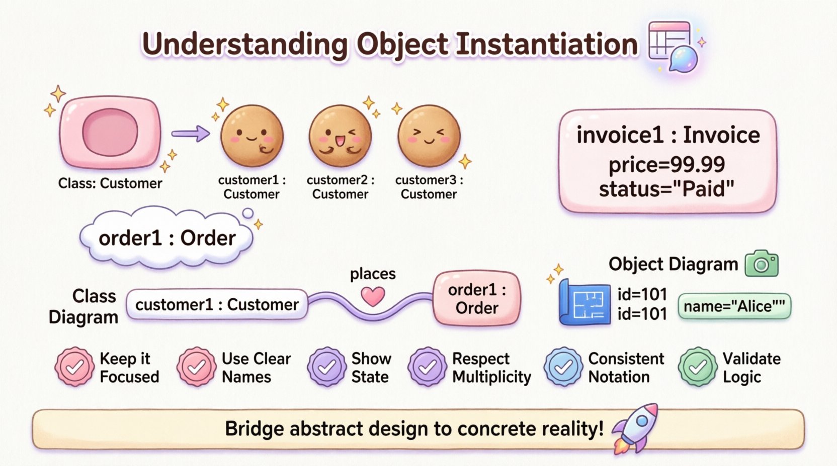
- Keep it Focused: Do not attempt to model the entire system in one diagram.
- Use Clear Names: Distinguish between class names and instance names clearly.
- Show State: Always include attribute values where relevant.
- Respect Multiplicity: Ensure links adhere to the cardinality defined in the class model.
- Use Consistent Notation: Follow standard UML conventions for naming and linking.
- Validate Logic: Check that the state of linked objects makes sense together.
By treating object instantiation as a critical component of your modeling process, you gain a deeper understanding of your system’s behavior. This leads to better designs, fewer bugs, and clearer communication among team members.
🚀 Moving Forward
Object instantiation is more than a technical detail; it is a lens through which we view the reality of software systems. By mastering the nuances of how instances are represented, named, and connected, you enhance your ability to design robust and reliable architectures. The object diagram serves as a bridge between the abstract world of classes and the concrete world of execution. Use it wisely to illuminate the path from design to deployment.
Remember that the goal is clarity. Whether you are debugging a critical error or explaining a complex feature to a client, a well-constructed object diagram can provide the insight needed to move forward with confidence.