Enterprise architecture requires more than just a collection of models; it demands a language that stakeholders can understand and trust. ArchiMate provides this language, offering a structured approach to visualize, analyze, and design complex organizations. However, the power of the method lies not in the symbols themselves, but in how they are applied. A cluttered diagram confuses; a well-structured model clarifies.
This guide outlines the essential practices for creating ArchiMate diagrams that communicate effectively. We will explore how to maintain consistency across layers, select appropriate viewpoints, and avoid common modeling errors that dilute the value of your architecture work.
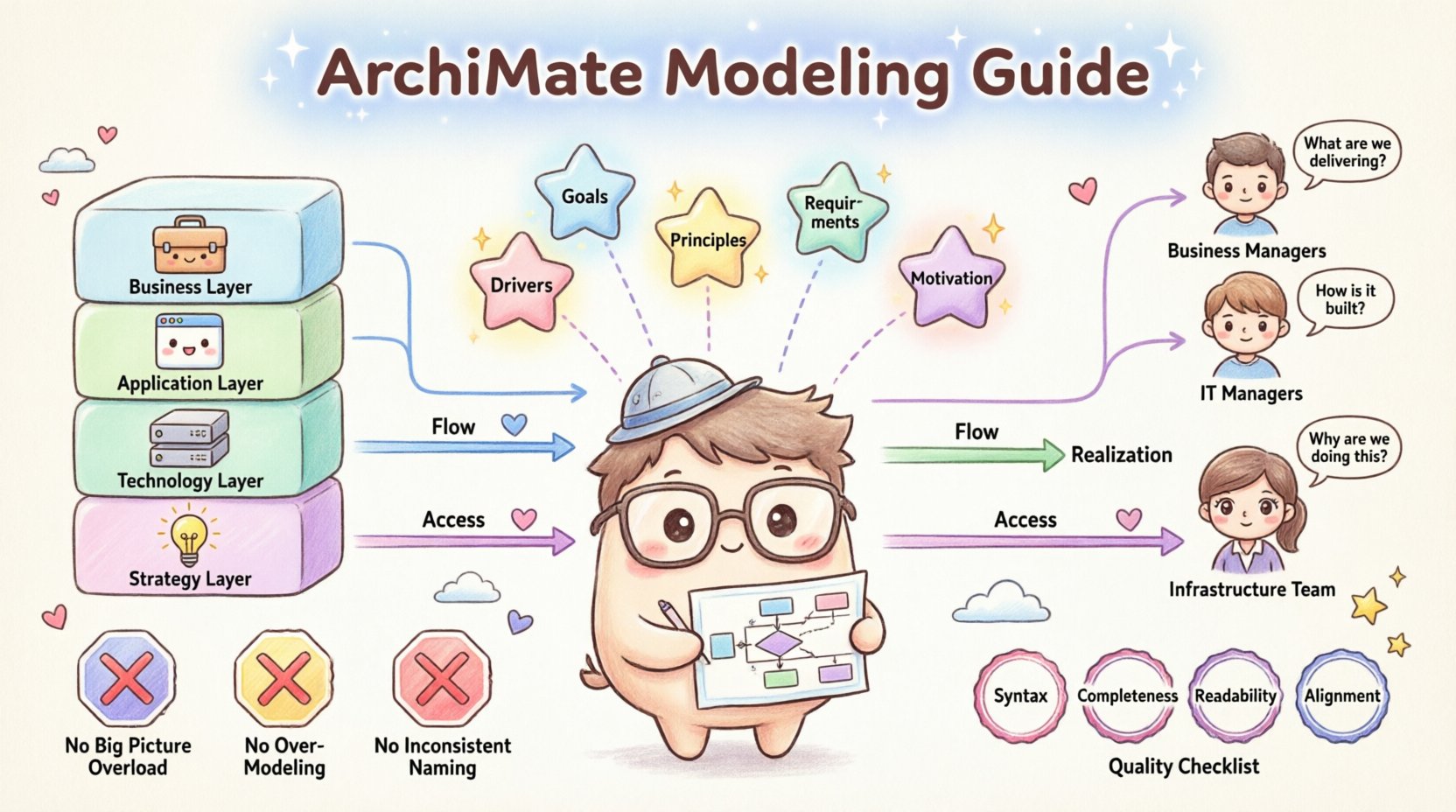
🧱 Understanding the Core Layers
The foundation of ArchiMate is its layered structure. This separation of concerns allows architects to zoom in on specific aspects of the enterprise without losing the broader context. Adhering to layer boundaries is crucial for clarity.
- Business Layer: Focuses on the business structure, business processes, and business services. This is where the organization’s strategy and value chain are defined.
- Application Layer: Describes the applications that support the business processes. It highlights software systems, data, and user interfaces.
- Technology Layer: Details the physical and logical infrastructure that runs the applications. This includes hardware, networks, and deployment environments.
- Strategy Layer: Connects the core layers to the motivation of the enterprise. It includes goals, principles, and requirements.
When creating a diagram, ask yourself which layer is the primary focus. Mixing too many layers without a clear purpose can lead to cognitive overload. For instance, a high-level strategic view should not dive into the specific hardware configurations of the technology layer unless that detail is critical to the decision being made.
🗺️ Selecting the Right Viewpoints
A single diagram cannot show everything. Different stakeholders require different information. Viewpoints define the perspective from which a view is constructed. Choosing the correct viewpoint ensures the right audience gets the right information.
| Viewpoint | Primary Audience | Focus Area |
|---|---|---|
| Business Process | Business Managers | Workflow and activities |
| Application Usage | IT Managers | Software support for processes |
| Deployment | Infrastructure Team | Physical topology |
| Goal Realization | Strategy Board | Alignment of actions to goals |
When modeling, do not default to a single generic view. Instead, tailor the diagram to the specific question being asked. If the question is “How does the system fail?”, a technology deployment view might be necessary. If the question is “What is the cost of change?”, a business capability view is more appropriate.
To ensure consistency, define a set of standard viewpoints for your organization. This prevents every architect from designing their own unique notation style, which creates fragmentation in the enterprise architecture repository.
🎨 Visual Consistency and Standards
Clarity is often a matter of visual discipline. When anyone looks at your diagram, they should immediately understand what the shapes and colors represent without needing a legend. Consistency reduces the time required to interpret the model.
Color Coding
While ArchiMate allows flexibility, using color to denote layers or specific types of elements helps visual scanning. For example, consistently using blue for business elements and green for technology elements creates a mental map for the reader. However, do not rely solely on color, as some stakeholders may have color vision deficiencies. Use shape or text labels as primary identifiers.
Labeling Conventions
Names must be descriptive and consistent. Avoid abbreviations unless they are standard across the enterprise. For example, use “Customer Management System” instead of “CMS”. This avoids confusion with other common acronyms. Ensure that every element has a unique identifier or name within the context of the model.
- Use Title Case: Maintain a consistent capitalization style for all labels.
- Avoid Redundancy: If an element is named “Customer Service Process”, do not label the related activity “Process Customer Service”. Be concise.
- Contextual Labels: Ensure the label makes sense within the diagram. A generic label like “System” is less useful than “Order Processing Engine”.
🔗 Managing Relationships Effectively
ArchiMate defines 12 types of relationships. These lines connect the elements and tell the story of the architecture. Overusing relationships, or using the wrong type, can turn a diagram into a tangled web.
Common Relationship Types
- Association: A general link between two elements. Use this sparingly.
- Flow: Indicates the movement of information or material between objects.
- Realization: Shows how an element implements or realizes another element.
- Access: Indicates that an object uses or accesses another object.
- Assignment: Shows an assignment of a role to an actor or a process.
When drawing lines, avoid crossing them unnecessarily. Crossing lines increase cognitive load and make the diagram harder to trace. If a relationship must cross a boundary, use an annotation or a bend to make the path clear. Use orthogonal lines (straight horizontal and vertical segments) rather than diagonal lines to maintain a clean, grid-like appearance.
Directionality
Relationships often have a direction. Ensure the arrowheads are visible and point in the logical direction of the flow or dependency. A common mistake is drawing undirected lines where a specific dependency exists. If element A depends on element B, the arrow should point from A to B to indicate the direction of the reliance.
🎯 Incorporating the Motivation Layer
Architecture without motivation is just a map without a destination. The Motivation layer explains why the enterprise is structured the way it is. It includes Goals, Principles, Requirements, and Drivers.
Integrating this layer into your diagrams helps stakeholders understand the justification behind architectural decisions. For example, if you propose a new application, show the Goal it supports. If you remove a process, show the Principle that drives the removal.
- Goals: High-level objectives the enterprise wants to achieve.
- Principles: Rules that guide decision-making.
- Requirements: Specific needs that must be met.
- Drivers: External or internal factors influencing the enterprise.
When modeling, try to link the core layers (Business, Application, Technology) to the Motivation layer. This creates a traceability chain. If a requirement is not linked to any architectural element, it may indicate a gap in the design. If an element is not linked to any goal, it may be a candidate for retirement.
🛑 Common Pitfalls to Avoid
Even experienced architects can fall into traps that reduce the quality of their models. Awareness of these common issues helps in maintaining high standards.
1. The “Big Picture” Trap
Attempting to show the entire enterprise in a single diagram is a recipe for disaster. Complexity explodes quickly, and the diagram becomes unreadable. Break down large models into smaller, manageable views. Use zooming techniques where a high-level view links to a detailed view, rather than cramming details into the main diagram.
2. Over-Modeling
Modeling every single relationship and element can create a model that is too detailed to be useful. Focus on the elements that matter for the specific context of the diagram. If a detail does not help answer the stakeholder’s question, it can often be omitted.
3. Ignoring the Context
Diagrams should not exist in a vacuum. Ensure that the context of the diagram is clear. Is this a view of the entire organization or a specific department? Is it a future state or a current state? Always include a clear title and, if necessary, a brief description of the scope.
4. Inconsistent Naming
If one part of the model uses “Process” and another uses “Activity” for the same concept, the model becomes confusing. Establish a glossary of terms and enforce it across all models. This ensures that when a stakeholder searches for a term, they find consistent results.
🔄 Maintenance and Governance
An architecture model is a living artifact. It requires maintenance to remain relevant. Without governance, models drift from reality, and their value diminishes over time.
- Version Control: Keep track of changes to the models. Knowing when a decision was made and by whom is vital for audits and future reference.
- Review Cycles: Schedule regular reviews of the architecture. Ensure that the models reflect the current state of the enterprise.
- Change Management: When a change is proposed, update the model to reflect the impact. This might involve updating relationships, adding new elements, or removing old ones.
- Stakeholder Feedback: Regularly seek feedback from the users of the diagrams. If they find a diagram confusing, ask why and adjust the visualization.
Documentation is part of the model. Include notes that explain complex relationships or decisions that are not obvious from the diagram alone. These annotations provide the necessary context for future architects who may not have been present when the original design was created.
📊 Structuring Complex Information
When dealing with complex scenarios, structure is key. Use grouping techniques to organize related elements. A group can represent a specific business unit, a specific project, or a specific time period.
Use nesting carefully. Nesting elements within other elements can show containment, but too much nesting hides relationships. If an element is nested inside another, ensure that this relationship is intentional and meaningful. Do not use nesting solely as a way to organize space on the canvas.
Consider using swimlanes for processes. Swimlanes clearly separate responsibilities between different roles or departments. This makes it easy to see handoffs and where bottlenecks might occur. For example, a swimlane diagram can show the flow of a request from the “Customer” lane to the “Sales” lane, and then to the “Fulfillment” lane.
🔍 Reviewing for Quality
Before finalizing a diagram, perform a quality check. This is a simple step that prevents errors from propagating to stakeholders.
- Syntax Check: Ensure all relationships are valid according to the ArchiMate specification. Some connections are not allowed between certain element types.
- Completeness Check: Are all necessary elements present? Is there a start and an end to the flow?
- Readability Check: Can a new person understand the diagram without asking questions? If not, simplify.
- Alignment Check: Do the diagrams align with the strategic goals? Is there a clear line of sight from the technology up to the business value?
By adhering to these practices, you ensure that your ArchiMate models serve their primary purpose: communication. A good diagram speaks louder than a thousand words. It provides a shared understanding of the enterprise, enabling better decisions and more effective execution of strategy.
The goal is not just to create a model, but to create a model that works. It should be a tool that architects, managers, and developers can use to navigate the complexity of the organization. With discipline, consistency, and a focus on clarity, ArchiMate becomes a powerful asset for enterprise transformation.