データベース設計におけるアーキテクチャ成熟度の重要性
エンティティ関係図(ERD)は効果的なシステムアーキテクチャの基盤となる。これらは静的な図示ではなく、三つの異なる段階で開発される。アーキテクチャ成熟度。各段階は、データベース設計ライフサイクルにおいて、特定の対象者、すなわちステークホルダーからデータベース管理者までに応じた独自の目的を果たす。すべての三つのレベルがエンティティ、属性、関係を含むものの、詳細の深さや技術的特異性はそれらの間で大きく異なる。
これらのモデルの進化を真正に理解するためには、建設のたとえを使うと役立つ。家を建てるのを想像してみよう:概念的ERDは、キッチンやリビングルームのような部屋の概略的な位置を示す建築家の初期スケッチである。論理的ERDは寸法や家具の配置を明確に示す詳細な平面図であるが、まだ素材の指定は含まれていない。最後に、物理的ERDはエンジニアリングの図面として機能し、正確な給排水設備、電気配線、および基礎に使用するコンクリートの特定のブランドを指定する。
1. 概念的ERD:ビジネス視点
この概念的ERDは最も高い抽象度を表す。ビジネスオブジェクトとその関係に対する戦略的視点を提供し、技術的なごちゃごちゃさを排除している。
目的と焦点
このモデルは主に要件収集および全体のシステムアーキテクチャの可視化に使用される。主な目的は、技術チームと非技術的ステークホルダーとの間のコミュニケーションを円滑にすることである。その焦点は、どのようなエンティティが存在するか——たとえば「学生」、「製品」、または「注文」など——を定義することに集中する。データベーステーブルにおけるこれらのエンティティの実装方法には焦点を当てない。
詳細度
概念的モデルは通常、技術的制約を欠く。たとえば、多対多の関係は、基数や結合テーブルの複雑さを伴わずに単に関係として描かれることが多い。特徴的に、この段階では一般化を用いることがある。たとえば「三角形」を「図形」のサブタイプとして定義するようなもので、これは後の物理的実装では抽象化される概念である。
2. 論理的ERD:詳細な視点
成熟度スケールを下っていくと、論理ERDは、概念モデルの強化版として、抽象的なビジネス要件と具体的な技術的実装の間のギャップを埋める役割を果たす。
目的と焦点
論理モデルは、高レベルの要件を運用およびトランザクションエンティティに変換する。これにより、明示的なカラム各エンティティに対して定義するが、厳密に特定のデータベース管理システム(DBMS)である。この段階では、最終的なデータベースがOracle、MySQL、またはSQL Serverのいずれになるかは問題にならない。
詳細度
概念モデルとは異なり、論理ERDはすべてのエンティティに属性を含む。しかし、データ型(例:整数 vs. 浮動小数点)や特定のフィールド長といった技術的な詳細を指定するまでには至らない。
3. 物理ERD:技術的ブループリント
この物理ERDは、リレーショナルデータベースの最終的で実行可能な技術設計を表す。これはデプロイされるスキーマである。
目的と焦点
このモデルは、特定のDBMS内でのデータベーススキーマ作成のためのブループリントとして機能する。論理モデルを拡張し、特定のデータ型、長さ、制約(例:varchar(255), int、またはnullable).
詳細度
物理ERDは非常に詳細である。正確な主キー(PK)および外部キー (FK)関係を厳密に強制するために。さらに、対象となるDBMSの特定の命名規則、予約語、制限事項を考慮しなければならない。
ERDモデルの比較分析
これらのアーキテクチャレベルの違いを要約するために、以下の表は異なるモデルで通常サポートされる機能を示している。
| 機能 | 概念的 | 論理的 | 物理的 |
|---|---|---|---|
| エンティティ名 | はい | はい | はい |
| 関係 | はい | はい | はい |
| 列/属性 | オプション/いいえ | はい | はい |
| データ型 | いいえ | オプション | はい |
| 主キー | いいえ | はい | はい |
| 外部キー | いいえ | はい | はい |
Visual ParadigmとAIによる設計の最適化
これらのモデルを手動で作成し、一貫性を保つのは手間がかかる場合があります。現代のツールであるVisual Paradigm自動化と人工知能を活用して、これらの成熟度レベル間の移行をスムーズにする。
モデル変換とトレーサビリティ
Visual ParadigmにはModel Transitorというツールが搭載されており、概念モデルから直接論理モデルを導出する、その後、論理モデルから物理モデルを導出する。このプロセスにより自動トレーサビリティが維持され、ビジネスビューの変更が技術的仕様書に正確に反映されることを保証する。
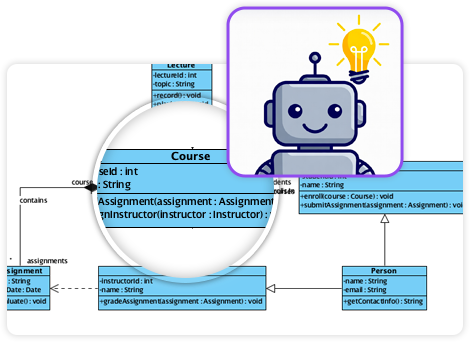
AI駆動の生成
高度な機能にはAI機能テキスト記述から即座にプロフェッショナルなERDを生成できる。AIはエンティティや外部キー制約を自動的に推論し、手動での設定時間を大幅に削減する。

双方向同期
重要なのは、このプラットフォームが双方向変換をサポートしていること。これにより、視覚的設計と物理的実装が同期した状態を保ち、ドキュメントが実際のコードベースからずれてしまうという一般的な問題を防ぐ。
-
スキーマ設計におけるDBModeler AIの包括的レビュー:DBModeler AIが自動化と知能によってデータベーススキーマ設計をどのように変革するかを詳細に分析。
-
DBModeler AI:インテリジェントなデータベースモデリングツール:Visual Paradigm内で、AI駆動のデータベースモデリングおよびスキーマ生成ツールにアクセス。
-
DBModeler AI:7段階ワークフローを備えたAI駆動のデータベース設計ツール。ドメインモデル、ER図、正規化されたスキーマ、完全な設計レポートを生成。ブラウザ上でライブのデータベースプレイグラウンドを起動し、即座にクエリをテスト。
-
AIテキスト分析 – テキストを自動的に視覚的モデルに変換:AIを活用してテキストドキュメントを分析し、UML、BPMN、ERDなどの図を自動生成することで、モデリングとドキュメント作成を迅速化。
-
Visual Paradigm ERDツール – オンラインでエンティティ関係図を作成: 直感的なドラッグアンドドロップ機能を活用して、ユーザーが簡単にデータベーススキーマを設計・可視化できる強力なウェブベースのERDツールです。
-
ERDツールを使ったデータベース設計 – Visual Paradigmガイド: データモデリングとスキーマ設計のベストプラクティスを活用して、堅牢でスケーラブルなデータベースをERDツールで設計するための包括的なガイド。
-
エンティティ関係図(ERD)とは何か? – Visual Paradigmガイド: ERDの詳細な説明、その構成要素、およびデータベース設計とデータモデリングにおける重要性。
-
無料ERDツール – Visual Paradigmでオンラインでデータベースを設計: インストールやサブスクリプションなしで、無料でオンラインでプロフェッショナルなエンティティ関係図を作成できるERDツールにアクセスできます。
-
Visual Paradigm ERDでエンティティを描く方法: Visual ParadigmのERDツールでエンティティを作成・カスタマイズするためのステップバイステップのユーザーガイド。正確なデータベースモデリングに役立ちます。
-
ERDでリレーショナルデータベースをモデリングする方法 – Visual Paradigmチュートリアル: ERDを使って、コンセプトから実装までリレーショナルデータベースをモデリングする方法を実践的に紹介するチュートリアル。