電子機器に特化したオンライン小売業者を想像してください。ピーク時のショッピング期間中に頻繁にタイムアウトが発生し、取引が失敗するという問題に直面していました。この問題は顧客の不満を引き起こすだけでなく、大きな収益損失にもつながりました。従来の決済処理フローの可視化手法は時間と手間がかかり、複雑でした。Visual ParadigmのAI図作成機能を活用することで、同社はアプローチを根本的に変革しました。かつて数時間、あるいは数日かかっていたプロセスが、わずか数秒に短縮されました。この記事では、Visual Paradigm AIが図の作成を単純化しただけでなく、決済処理フローの効率を著しく向上させた方法について学びます。その結果は?顧客満足度の向上と売上の増加です。
シーケンス図とは何ですか?
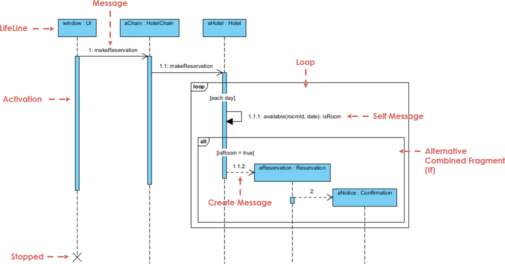
A シーケンス図は、プロセスがどのように相互に作用し、どのような順序で動作するかを示すインタラクション図の一種です。システム内で特定の機能を実行するために必要なオブジェクト間のメッセージのやり取りの順序を、時間の経過とともに示します。シーケンス図は、ソフトウェア開発やシステム工学でよく使用され、特に特定の機能のモデリングに用いられます。開発者がアプリケーション内の制御およびデータの流れを可視化するのに役立ち、複雑なプロセスを理解する上で不可欠です。
シーケンス図の典型的な利用事例には以下が含まれます:
- さまざまな機能的シナリオにおけるユーザーとシステムとの相互作用をモデル化する。
- 決済処理、注文管理、ユーザー認証などのプロセスのワークフローを可視化する。
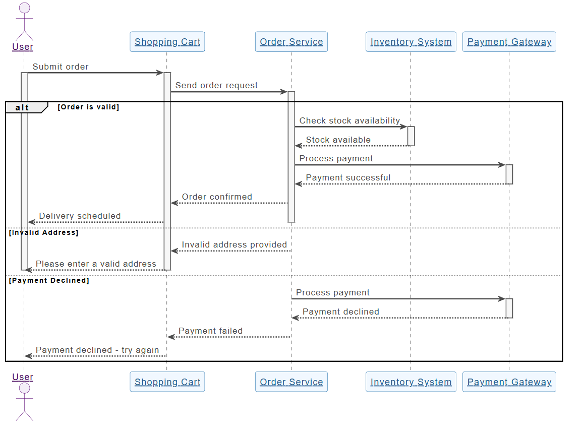
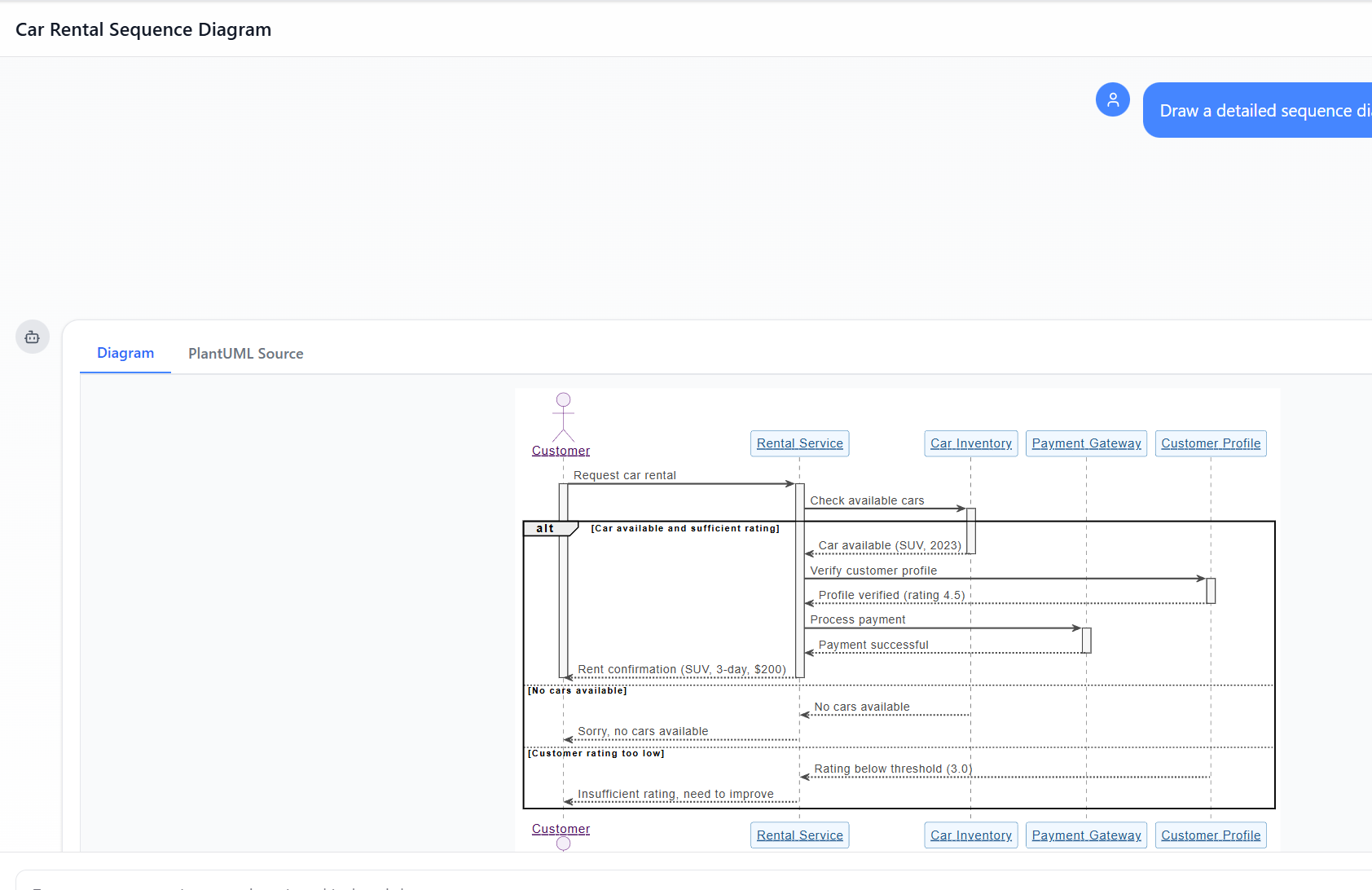
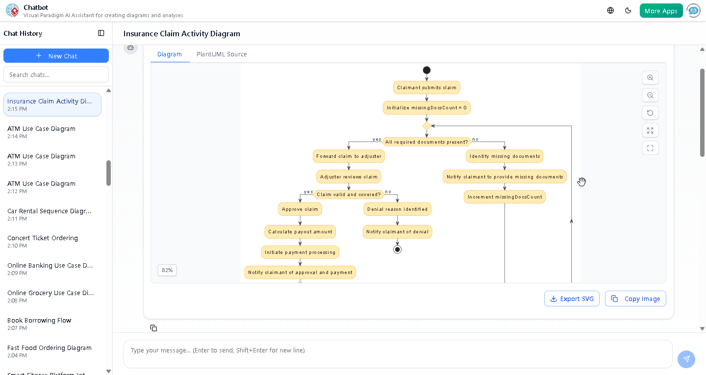
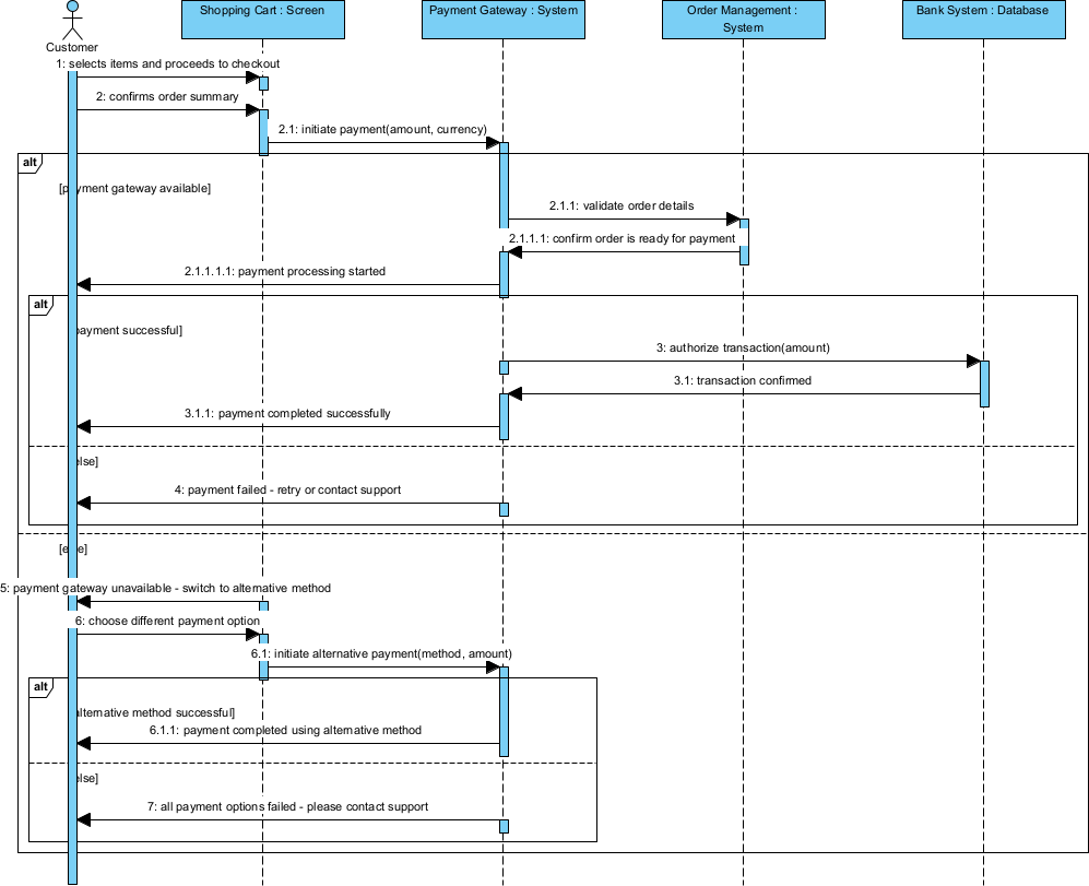
たとえば、決済処理システムでは、シーケンス図により、顧客の選択から支払い確認までの各ステップを明確に示すことができ、ユーザーインターフェース、決済ゲートウェイ、データベースなどのさまざまなシステムコンポーネント間の相互作用を強調できます。
チェックアウト時の決済処理フロー最適化プロジェクトの概要
オンライン小売業界では、迅速かつ効率的なチェックアウトプロセスが不可欠です。電子機器小売業者にとって、ピーク時のショッピングシーズンに頻繁にタイムアウトや支払い失敗が発生し、改善の必要性が高まりました。同社は、既存の決済処理フローが不十分に設計されていることに気づき、顧客の不満や売上機会の喪失を招いていました。この重要なプロセスを可視化し最適化するためにシーケンス図が必要でしたが、手作業による図の作成は煩雑で、重要な改善を遅らせる原因となっていました。
主な課題は以下の通りです:
- 忙しい時間帯に頻繁にシステムのタイムアウトが発生し、取引が失敗する。
- 決済フローの明確な可視化が不足しており、ボトルネックの特定が困難だった。
- 手作業による図の設計は時間のかかる作業であり、問題への迅速な対応を妨げた。
- 既存のフローについてチームメンバーおよびステークホルダーを一致させるのが難しく、効果的なコミュニケーションが困難だった。
なぜAIでシーケンス図を生成するのか?
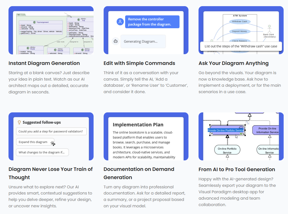
- 複雑なプロセスを正確に表現する図を即座に作成できる。
- 後で修正できるベース図を迅速に生成することで、時間を節約できる。
- チームメンバーおよびステークホルダー間での理解と合意を容易にする。
- 迅速なプロトタイピング文化を支援し、ビジネスプロセスの迅速な反復を可能にする。
AIによるシーケンス図の生成は、初期アイデア段階、迅速なプロトタイピング、ステークホルダーの合意形成ワークショップにおいて大きな価値を提供します。Visual Paradigmを活用することで、チームは迅速に代替案を検討し、改善のための堅実な出発点を作成でき、品質を損なうことなくコスト感度の高いプロジェクトに集中できます。即時なAI生成と包括的なプロフェッショナルモデリングプラットフォームの組み合わせにより、スムーズなワークフローが実現され、全体のプロジェクト効率が向上します。
Visual Paradigm Desktopで数秒でシーケンス図を生成する方法
- 起動する Visual Paradigm Desktop ProfessionalまたはEnterprise Edition.
- メニューへ移動する ツール → AI図生成.
- AI図表生成ウィンドウで「シーケンス図」を選択してください。
- 「トピック」フィールドに、明確な英語による説明を記入してください。
このケースにおける推奨されるプロンプト例:
「チェックアウト時の決済処理フローを最適化し、トランザクションのタイムアウトを削減し、顧客満足度を向上させる。」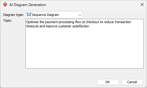
- 「OK」.
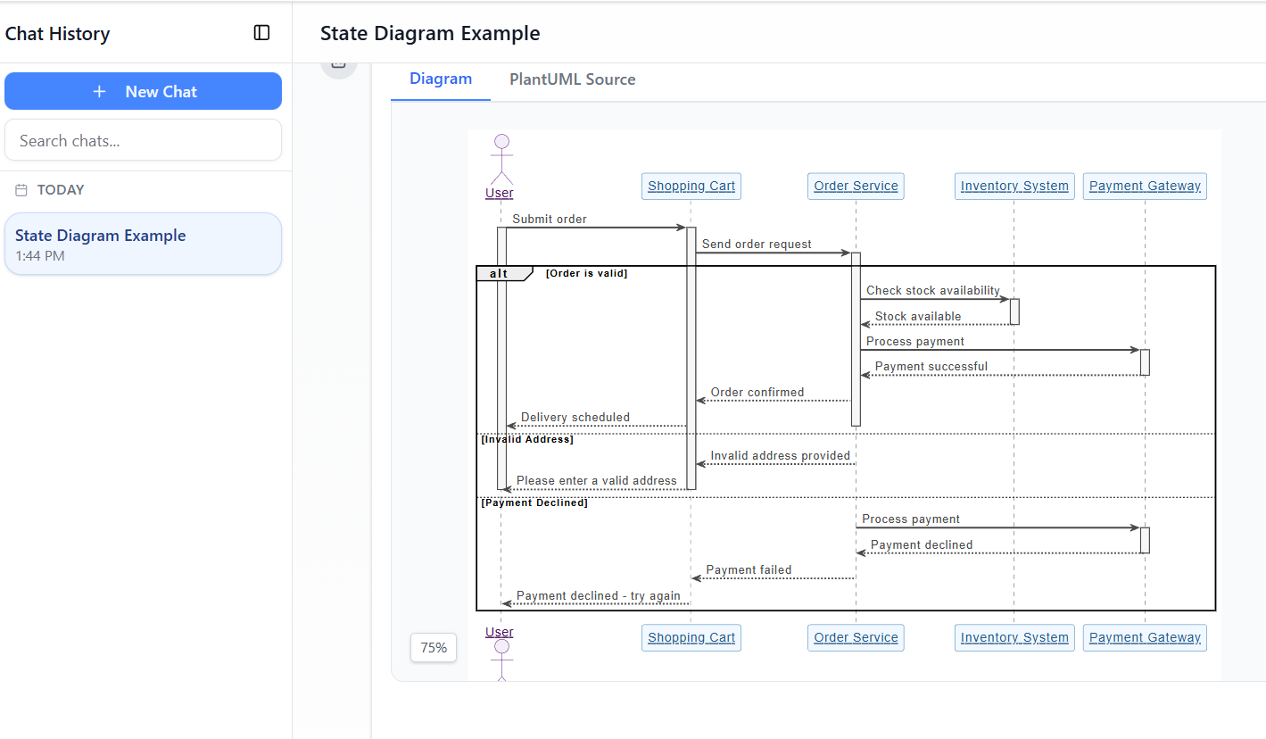
AIは数秒でクリーンで編集可能な図表を生成します。
AI生成図表のレビューと改善
AIは優れた出発点を提供します——詳細な調整こそが、プロフェッショナルなモデリングツールの真の強みです。
迅速な視覚的・構造的修正
AI生成されたシーケンス図を改善するためには、視覚的明確性を高めるために図形の位置を再調整したり、自動レイアウト機能を利用して視覚的フローをスムーズにしたり、ブランドに合わせて色のテーマを変更したり、コンテキストを明確にするために注記やコメントを追加したり、線をまっすぐに整えてプレゼンテーションを向上させるなどの簡単で効果的なアドバイスを検討してください。これらの調整により、最終的な図表は機能性だけでなく、視覚的にも魅力的になります。
このシーケンス図に完全なモデリング機能を活用する
生成されたシーケンス図は、包括的なモデリングツールへと進化でき、継続的なプロセス改善の中心となります。たとえば、初期の図表を改善した後、チームは以下の作業が可能になります:
- より詳細な決済ステップやエラー処理プロトコルを表現するために、ネストされたサブ図を生成する。
- 図表を要件トレーサビリティマトリックスとリンクし、開発プロセス全体ですべての決済処理要件が追跡されることを保証する。
- 図表から開発者向けのコードスタブを生成し、既存のソフトウェアコンポーネントとのシームレスな統合を可能にする。
- シミュレーションを実施し、混雑時における変更が顧客とのやり取りにどのように影響するかを可視化する。
これらの要素を統合することで、シーケンス図は静的な視覚資料から動的リソースへと進化し、チーム間の協働と共有理解を促進しながら、決済処理ワークフローの継続的な改善を推進します。
成果と主な教訓
- 最適化により、**トランザクション障害が30%削減**され、顧客満足度が著しく向上しました。
- 図表の設計および修正に費やしていた時間は**80%以上削減**され、チームは戦略的な改善に集中できるようになりました。
- 決済プロセスに関する明確なコミュニケーションにより、チーム間の協働と整合性が向上しました。
古くなった手作業プロセスからAI駆動の生成へと変革することで、直近の課題を解決しただけでなく、継続的な改善の基盤を築きました。ここでの広い教訓は、Visual Paradigm AIのような先進的なツールをワークフローに統合することで、競争の激しい市場におけるデジタルビジネスの成功を支えることができるということです。
結論
「Visual ParadigmAI図生成機能は、効率的なモデル化ソリューションを必要とする企業にとって画期的なものである。今日、Visual Paradigm Desktopをダウンロードして、60秒以内に最初のAI生成図を制作しよう。