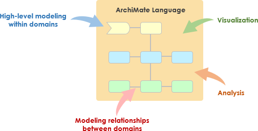
ArchiMate について
ArchiMate は、ビジネスドメイン内および across でアーキテクチャの記述、分析、可視化を支援するオープンで独立した企業アーキテクチャモデリング言語です。複雑なアーキテクチャをステークホルダーに明確かつ曖昧のない方法で伝えることを目的として設計されています。ArchiMate は、TOGAF アーキテクチャ開発手法(ADM)と併用する場合特に有用であり、企業アーキテクチャをモデル化および伝達するための標準化された方法を提供します。
ArchiMate の主要な概念
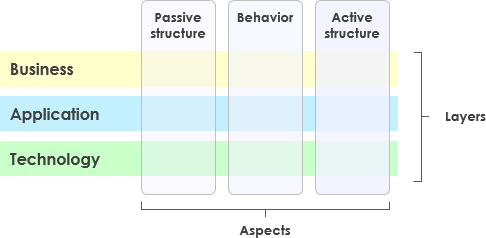
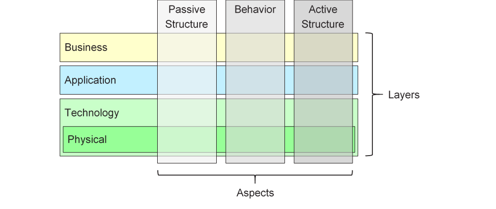
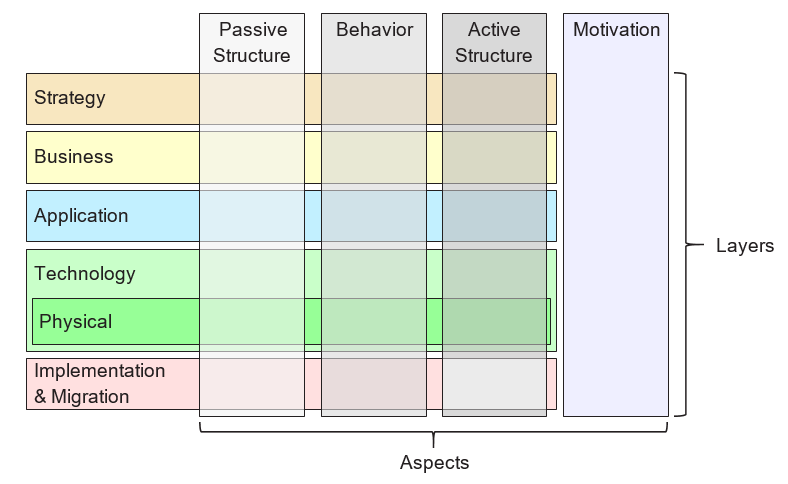
1. ArchiMate のレイヤー
ArchiMate は企業アーキテクチャを3つの主要なレイヤーに分類する:
- ビジネスレイヤー:組織の目標を支援するビジネスプロセス、サービス、機能に焦点を当てる。
- アプリケーションレイヤー:ビジネスレイヤーを支援するアプリケーションサービス、コンポーネント、およびそれらの相互作用を扱う。
- テクノロジー・レイヤー:アプリケーションレイヤーを支援するハードウェア、ソフトウェア、ネットワークコンポーネントを含むテクノロジーインフラをカバーする。
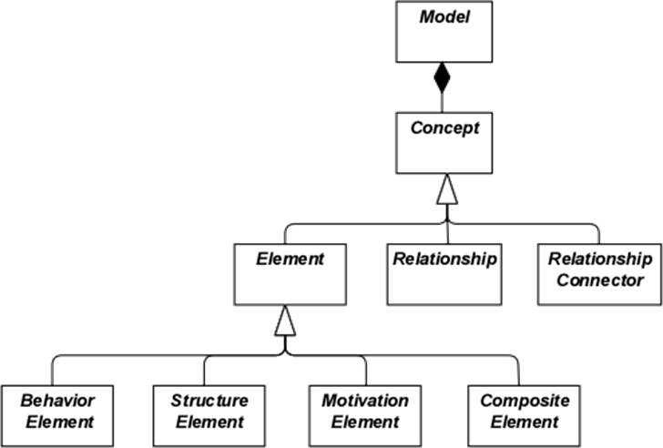
2. コア要素
ArchiMate は、アーキテクチャをモデル化するために使用されるいくつかのコア要素を定義している:
- アクティブ構造要素:行動を実行するエンティティを表す。ビジネスアクター、アプリケーションコンポーネント、デバイスなど。
- 行動要素:アーキテクチャ内のプロセス、機能、サービス、相互作用を表す。
- パッシブ構造要素:行動要素によって使用または生成される情報やデータを表す。ビジネスオブジェクトやデータオブジェクトなど。
3. 関係
ArchiMate は、要素を接続するためのいくつかの種類の関係を定義している:
- 構造的関係:コンポジション、集約、特殊化など。
- 依存関係:関連、実現、使用されるなど。
- 動的関係: たとえば、トリガーとフロー。
4. 視点
ArchiMateは、異なる視点からアーキテクチャを可視化するための複数の視点を提供しています:
- ビジネスプロセス視点: ビジネスプロセスとその相互作用を示します。
- アプリケーション協働視点: アプリケーションがビジネスプロセスを支援するためにどのように協働するかを示します。
- 技術実現視点: 技術コンポーネントがアプリケーションコンポーネントをどのように実現するかを示します。
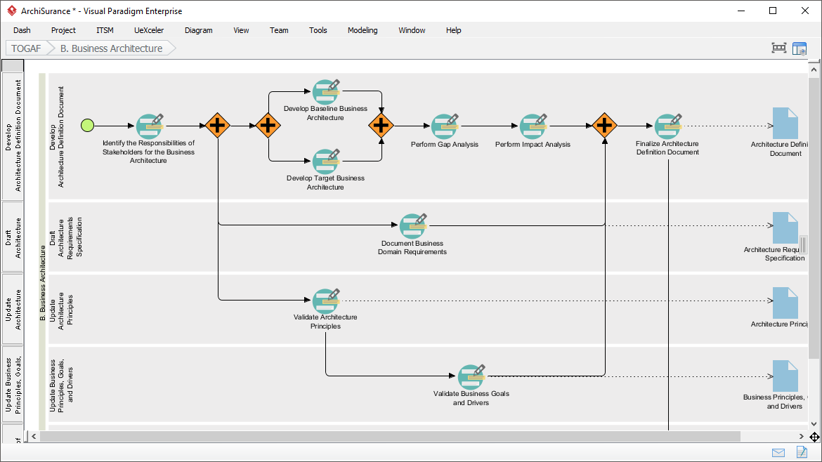
ArchiMateとTOGAF ADM
TOGAFアーキテクチャ開発手法(ADM)
TOGAF ADMは、企業アーキテクチャを構築するための包括的な手法です。複数の段階から構成されており、それぞれがアーキテクチャ開発プロセスの特定の側面に焦点を当てています。ArchiMateは、各段階でアーキテクチャをモデル化および可視化するための標準化された方法を提供することで、TOGAF ADMを支援しています。
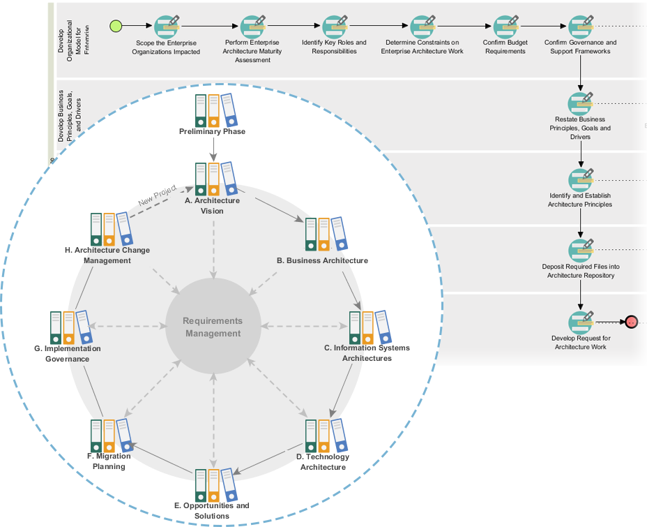
TOGAF ADMの段階
- 準備段階: アーキテクチャの原則、フレームワーク、ガバナンスを確立します。
- アーキテクチャビジョン: 範囲、ステークホルダー、関心事、およびビジネス目標を定義します。
- ビジネスアーキテクチャ: ビジネスプロセスやサービスを含むビジネスアーキテクチャを開発します。
- 情報システムアーキテクチャ: データアーキテクチャおよびアプリケーションアーキテクチャを開発します。
- 技術アーキテクチャ: 技術アーキテクチャを開発します。
- 機会と解決策: アーキテクチャプロジェクトを特定し、優先順位を付けています。
- 移行計画: 移行および実装計画を開発します。
- 実装ガバナンス: アーキテクチャの実装に対するガバナンスと支援を提供します。
ArchiMateモデルの例
この図は、医療管理システムのレイヤードアーキテクチャを示しており、主に2つのレイヤーに分かれています:アプリケーションレイヤー および テクノロジーレイヤー。各コンポーネントおよびそれらの相互作用について詳しく説明します:
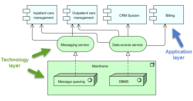
アプリケーションレイヤー(青)
このレイヤーは、医療サービスを管理するためにユーザーまたは他のシステムと直接やり取りするさまざまなアプリケーションやシステムで構成されています。このレイヤーの主要なコンポーネントは以下の通りです:
-
入院患者ケア管理:
- 病院に入院している患者に関連するサービスおよびプロセスを管理します。
-
外来患者ケア管理:
- 入院せずに治療のために病院を訪れる患者のサービスおよびプロセスを管理します。
-
CRMシステム(顧客関係管理):
- 患者とのやり取りを管理し、コミュニケーション、フォローアップ、患者関係の管理を含みます。
-
請求:
- 財務関連の業務を処理し、請求書の作成、支払い処理、財務記録の管理を含みます。
テクノロジーレイヤー(緑)
このレイヤーは、アプリケーションレイヤーのアプリケーションを支える基盤インフラおよびサービスを提供します。このレイヤーの主要なコンポーネントは以下の通りです:
-
メッセージングサービス:
- 医療管理システム内の異なるアプリケーションおよびシステム間の通信を促進します。
- メッセージが信頼性を持って、正しい順序で届くことを保証します。
-
データアクセスサービス:
- システム全体にわたってデータにアクセスおよび管理するための集中化された方法を提供します。
- データの取得および保存が効率的かつ安全に行われることを保証します。
-
メインフレーム:
- コアサービスおよびデータをホストする中央コンピューティングシステム。
- 以下の2つの主要なコンポーネントを含む:
- メッセージキューイング:メッセージのキューイングおよび処理を管理し、信頼性の高い通信を確保する。
- DBMS(データベース管理システム):さまざまなアプリケーションで使用されるデータを格納および管理する。
相互作用
- 入院患者ケア管理, 外来患者ケア管理, CRMシステム、および請求は、以下のものと相互作用するメッセージングサービスおよびデータアクセスサービスそれぞれの機能を実行するために。
- このメッセージングサービスおよびデータアクセスサービスは以下のものに依存するメインフレームコアサービス(メッセージキューイングやデータベース管理など)を提供する。
- このメインフレームメッセージが正しく処理され、データが効率的に管理されることを保証し、システム全体の運用を支援します。
この図は、アプリケーションレベルの機能と基盤となる技術インフラストラクチャを分離することで、医療サービスを構造的に管理するアプローチを示しています。この分離により、モジュール性と保守性の高いシステム設計が可能となり、一方のレイヤーでの変更が他方への影響を最小限に抑えることができます。メッセージングサービス および データアクセスサービスこれらは中間役を果たし、アプリケーションコンポーネントとメインフレームの間での通信およびデータ管理を促進します。
推奨されるArchiMate EAツール
Visual Paradigmは、エンタープライズアーキテクチャ(EA)プロジェクトにおけるArchiMateモデリングの最良のツールの一つとして広く認識されています。以下に、それが強く推奨される理由を示します:
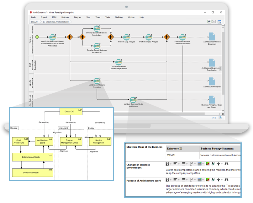
1. 包括的なArchiMateサポート
- 完全なArchiMate標準:Visual Paradigmは最新のArchiMate標準、ArchiMate 3.1をサポートしており、公式のArchiMate要素および関係性をすべて使用してモデリングできるようにしています。
- 豊富な要素ライブラリ:豊富なArchiMate記号のライブラリを提供しており、詳細で正確なモデル作成が容易になります。
2. 使いやすいインターフェース
- 直感的なデザイン:ユーザーが直感的に操作できる使いやすいインターフェースを提供しており、ArchiMateモデリングに初めて触れるユーザーにも扱いやすいです。
- ドラッグアンドドロップ:ドラッグアンドドロップ機能により、迅速かつ効率的なモデル作成が可能になります。
3. 高度なモデリング機能
- レイヤードビュー:ビジネス、アプリケーション、テクノロジーなど、レイヤードビューの作成をサポートし、エンタープライズアーキテクチャの包括的な視点を提供します。
- レイヤー間の関係:アーキテクチャの異なるレイヤー間の関係を簡単に定義および可視化できます。
4. 協働と共有
- チーム協働:Visual Paradigmは協働作業をサポートしており、複数のユーザーが同時に同じプロジェクトに取り組むことができます。
- バージョン管理:統合されたバージョン管理により、変更の管理とモデルの進化の追跡が可能になります。
5. 統合機能
- ツール統合:JIRA、Confluence、さまざまなデータベースなど、他のツールやプラットフォームとシームレスに統合され、全体のEA実践を強化します。
- インポート/エクスポート:ArchiMate交換ファイル形式を含むさまざまなフォーマットでのモデルのインポートおよびエクスポートをサポートし、他のツールとの互換性を確保します。
6. ドキュメント作成とレポート作成
- 自動ドキュメント作成:ArchiMateモデルから包括的なドキュメントを自動生成し、時間の節約と一貫性の確保を実現します。
- カスタムレポート:特定のステークホルダーのニーズに合わせたカスタムレポートの作成を可能にします。
7. トレーニングとサポート
- 豊富なリソース:ユーザーが始めやすく、ArchiMateモデリングを習得できるよう、多数のチュートリアル、ガイド、例を提供します。
- カスタマーサポート:発生する可能性のあるあらゆる問題や質問に対応する強力なカスタマーサポートを提供します。
8. スケーラビリティ
- スケーラブルなソリューション:小規模および大規模なEAプロジェクトの両方に適しており、あらゆる規模の組織にとって汎用的なツールです。
9. コンプライアンスと標準
- 業界標準:業界標準およびベストプラクティスに準拠しており、EAモデルのコンプライアンスと最新性を確保します。
結論
ArchiMateは、TOGAF ADMメソドロジーを支援する強力で標準化された企業アーキテクチャのモデリング方法を提供します。ArchiMateの主要なコンセプト、レイヤー、要素、関係性を理解することで、ステークホルダーに対して複雑なアーキテクチャを効果的にモデリングおよび伝達できます。提示された例は、ArchiMateがビジネスプロセス、アプリケーション連携、テクノロジー実現をモデリングするのにどのように使用できるかを示しており、TOGAF ADMのさまざまなフェーズを支援します。
ArchiMateツールリソース
-
無料オンラインArchiMate図作成ツール
- 説明: ArchiMate 3の視覚的モデリング言語をサポートする無料のツールで、オンラインでArchiMate図を作成できます。始めやすくなるように例やテンプレートも用意されています。
- URL: 無料オンラインArchiMate図作成ツール 1
-
メインページ – 無料のArchiMateリソース
- 説明: 企業アーキテクチャをモデル化・記録するための視覚的言語を提供し、異なる領域内および領域間の関係を可視化する手段を提供します。
- URL: メインページ – 無料のArchiMateリソース 2
-
Visual Paradigm – UML、アジャイル、PMBOK、TOGAF、BPMNなど
- 説明: 業界独自のTOGAF ADMライフサイクルツールに加え、DoDAF、NAF、MODAFツールを提供し、主要企業から信頼されています。ArchiMateおよびその他のモデリングツールも含まれます。
- URL: Visual Paradigm – UML、アジャイル、PMBOK、TOGAF、BPMNなど 3
-
第7章. ArchiMate – Visual Paradigmコミュニティサークル
- 説明: 企業アーキテクトがビジネスドメイン間の関係を記述・分析・可視化するのを支援するツールを提供します。
- URL: 第7章. ArchiMate – Visual Paradigmコミュニティサークル 4
-
ArchiMateとは何か?
- 説明: ArchiMateのステップバイステップ学習ガイドで、企業アーキテクチャモデリングにどのように使用するかを含んでいます。
- URL: ArchiMateとは何ですか? 5
-
ArchiMateツール
- 説明: アジャイルソフトウェアチーム向けに設計された設計および管理ツールであるVisual Paradigmの使い方を学びます。
- URL: ArchiMateツール 6
-
最高のArchiMateソフトウェア
- 説明: 効果的なEA設計およびモデリング向けの認定ArchiMateツール。The Open Groupの公式仕様に準拠したArchiMate図を迅速に作成できます。
- URL: 最高のArchiMateソフトウェア 7
-
ArchiMate要素のフォーマット方法は?
- 説明: サイズの変更や色の変更などの操作を行うことで、ArchiMate要素を編集する方法を学びます。
- URL: ArchiMate要素のフォーマット方法は? 8
-
ArchiMate Viewpointガイド – リソースマップViewpoint
- 説明: 明確な説明と例を提供する包括的なArchiMate Viewpoint学習ガイド。
- URL: ArchiMate ビューポイントガイド – リソースマップ ビューポイント 9
-
ArchiMate ダイアグラム チュートリアル
- 説明: ArchiMate ダイアグラムについて学び、作成方法や使用タイミングを理解するのに役立つチュートリアルです。例やヒントを含んでいます。
- URL: ArchiMate ダイアグラム チュートリアル 10
これらのリソースは、企業アーキテクチャモデリングにVisual ParadigmのArchiMateツールを使用するための包括的な出発点を提供するはずです。