Understanding the static structure of a software system is fundamental to effective design. While class diagrams provide the blueprint, object diagrams offer a snapshot of the system in action at a specific moment. This guide addresses the most common queries regarding Object Diagrams, providing clear, authoritative answers for students and practitioners alike. We will explore definitions, notation, usage, and relationships without relying on specific tools or software products.
1. What exactly is an Object Diagram? 🏗️
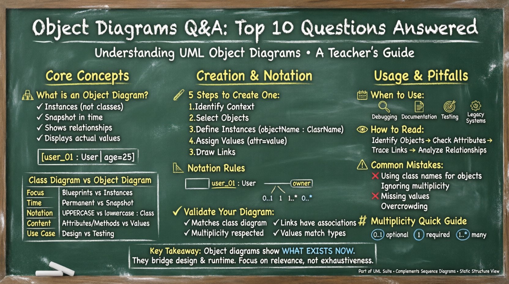
An object diagram is a type of static structure diagram in the Unified Modeling Language (UML). It depicts a set of objects and their relationships at a specific point in time. Unlike a class diagram, which defines types and potential structures, an object diagram shows actual instances.
- Instances: It represents specific objects, not just classes.
- Snapshot: It captures a moment, similar to a photograph of the system state.
- Relationships: It illustrates links between these instances, showing how they interact.
- Values: It displays actual attribute values assigned to the objects.
For example, while a class diagram defines a User class with an age attribute, an object diagram shows User_01 with age = 25. This distinction is crucial for understanding how the design translates into runtime behavior.
2. How does an Object Diagram differ from a Class Diagram? 🔄
Confusion often arises between class and object diagrams because both deal with structure. However, their purposes diverge significantly. The table below clarifies the distinction.
| Feature | Class Diagram | Object Diagram |
|---|---|---|
| Focus | Blueprints and Types | Instances and States |
| Time | Static (Permanent) | Snapshot (Specific Moment) |
| Notation | Class Name (Uppercase) | Instance Name (Lowercase + Class Name) |
| Content | Attributes and Methods | Attribute Values |
| Use Case | Design Phase | Documentation and Testing |
A class diagram answers “What can exist?”. An object diagram answers “What exists right now?”. Both are essential for comprehensive system modeling.
3. How do you create an Object Diagram from scratch? ✍️
Creating an object diagram requires a logical flow to ensure accuracy. Follow these steps to build a valid representation:
- Identify the Context: Determine which part of the system you are examining. Is it a specific process or a general state?
- Select Objects: Choose the instances that exist in this scenario. Do not include every possible object, only relevant ones.
- Define Instances: Name each object using the format
objectName : ClassName. This explicitly links the instance to its type. - Assign Values: Set attribute values for each object. Use
attributeName = value. - Draw Links: Connect objects based on relationships defined in the class diagram. Indicate multiplicity if applicable.
Ensure that every link drawn corresponds to a valid association in the underlying class structure. Do not invent relationships that do not exist in the design.
4. What are the standard symbols and notation rules? 📐
Consistency in notation is key to readability. UML provides strict guidelines for object diagrams.
- Object Box: A rectangle divided into two compartments. The top shows the name, and the bottom lists attributes.
- Object Name: Typically written in bold or underlined text. It often includes a colon, like
customer_01 : Customer. - Links: Solid lines connecting objects. They represent associations.
- Role Names: Labels on links indicating the role an object plays in the relationship.
- Multiplicity: Numbers or ranges (e.g.,
0..1,1..*) placed near the ends of links. - Navigation Arrows: Optional arrows indicating direction of traversal.
Remember, object diagrams use the same relationship types as class diagrams, such as aggregation, composition, and inheritance, though inheritance is less common in object snapshots.
5. When is it appropriate to use an Object Diagram? 📅
Not every situation requires an object diagram. Use them strategically to enhance communication and understanding.
- Explaining Complex Scenarios: When a sequence of events is hard to describe textually, a static snapshot can clarify the state.
- Debugging: Visualizing the state during a specific error condition helps trace issues.
- Documentation: Providing examples of valid data structures for developers.
- Testing: Creating test cases based on specific object states to ensure requirements are met.
- Legacy Systems: Documenting the current state of a system where class diagrams are outdated.
Overusing object diagrams can lead to maintenance issues, as they become outdated quickly. Limit their use to high-value scenarios.
6. How do you read and interpret an Object Diagram? 👀
Reading an object diagram is like reading a map of a specific city block at a specific time. Start by identifying the objects and their types.
- Read the Instances: Look at the top of each box to identify the object name and its class.
- Check the Attributes: Look at the bottom compartment to see current values. This reveals the state.
- Trace the Links: Follow the lines to see connections. Note the multiplicity to understand cardinality.
- Identify Isolated Objects: Objects without links might indicate orphaned data or specific initialization states.
- Analyze Relationships: Determine if the relationships are one-to-one, one-to-many, or many-to-many based on the link ends.
Interpretation requires understanding the semantics of the links. A link labeled owns implies a different relationship than one labeled belongs_to.
7. What are common mistakes made by beginners? ⚠️
New modelers often struggle with precision. Avoid these frequent errors to maintain diagram integrity.
- Using Class Names for Objects: Do not label objects simply as
User. Useuser_01 : Userto distinguish instance from type. - Ignoring Multiplicity: Failing to label links with multiplicity creates ambiguity about how many instances are involved.
- Missing Attribute Values: An object diagram without values is just a class diagram. Ensure data is present.
- Incorrect Link Types: Drawing a generalization link (inheritance) between objects is usually incorrect. Use associations instead.
- Inconsistent Naming: Mixing camelCase and snake_case can confuse readers. Stick to a consistent convention.
- Overcrowding: Trying to show every object in a system makes the diagram unreadable. Focus on the relevant subset.
Review your diagrams against the class diagram to ensure consistency. Every link in the object diagram must be supported by an association in the class diagram.
8. How does an Object Diagram relate to a Sequence Diagram? 📊
Both diagrams are part of the UML suite but serve different purposes. Confusing them is a common pitfall.
- Object Diagram: Represents Static structure. It shows what exists and how they are connected at a point in time. It is a structural view.
- Sequence Diagram: Represents Dynamic behavior. It shows interactions over time, including messages and method calls. It is a behavioral view.
You might use an object diagram to define the participants in a sequence diagram. The sequence diagram then explains how those objects interact. They complement each other but should not be confused.
9. How do you handle multiplicity and cardinality? 🔢
Multiplicity defines constraints on the number of instances that can participate in a relationship. In object diagrams, this is visually represented at the ends of links.
- Zero or One (0..1): The object may or may not be connected to another.
- Exactly One (1): The object must be connected to exactly one other.
- Zero or More (0..*): The object can be connected to any number, including none.
- One or More (1..*): The object must be connected to at least one other.
- Specific Range (2..4): The object must be connected to between two and four others.
When drawing, place the multiplicity notation near the relevant object end. This ensures that the specific instance complies with the structural rules defined in the class diagram.
10. How do you validate the accuracy of an Object Diagram? ✅
Validation ensures the diagram represents a valid state of the system. Follow these checks before finalizing the diagram.
- Check Class Consistency: Ensure every object instance corresponds to a defined class in the system design.
- Verify Link Existence: Ensure every link drawn exists as an association in the class diagram.
- Confirm Multiplicity: Check that the number of links per object matches the multiplicity constraints.
- Review Attribute Values: Ensure data types match the definitions (e.g., integers for age, strings for names).
- Assess Completeness: Determine if the diagram captures all necessary information for the specific use case.
Validation is an iterative process. As the design evolves, the object diagram must be updated to reflect the current reality of the system state.
Summary of Key Takeaways 📝
Object diagrams are powerful tools for visualizing system states. They bridge the gap between abstract design and concrete implementation. By understanding the difference between classes and instances, mastering notation, and adhering to validation rules, you can create diagrams that communicate complex information effectively. Remember to focus on relevance and accuracy rather than exhaustive detail. This approach ensures your documentation remains useful and maintainable throughout the development lifecycle.