Znaczenie dojrzałości architektonicznej w projektowaniu baz danych
Diagramy relacji encji (ERD) stanowi fundament skutecznej architektury systemu. Nie są to statyczne ilustracje, ale są tworzone w trzech różnych etapach dojrzałości architektonicznej. Każdy etap ma unikalne zadanie w ramach cyklu projektowania bazy danych, uwzględniając specyficzne grupy odbiorców, od interesariuszy po administratorów baz danych. Choć wszystkie trzy poziomy obejmują encje, atrybuty i relacje, stopień szczegółowości i specyfika techniczna znacznie się różnią między nimi.
Aby naprawdę zrozumieć postępowanie tych modeli, pomocne jest użycie analogii budowlanej. Wyobraź sobie budowę domu: koncepcyjny ERD to początkowy szkic architekta pokazujący ogólną lokalizację pomieszczeń, takich jak kuchnia i salon. logiczny ERD to szczegółowy plan piętra określający wymiary i rozmieszczenie mebli, choć jeszcze nie określa materiałów. Na końcu fizyczny ERD pełni rolę projektu inżynierskiego, określając dokładne instalacje kanalizacyjne, instalacje elektryczne oraz konkretną markę betonu dla fundamentu.
1. Koncepcyjny ERD: widok biznesowy
koncepcyjny ERDreprezentuje najwyższy poziom abstrakcji. Zapewnia strategiczny widok na obiekty biznesowe i ich relacje, bez zbędnych elementów technicznych.
Cel i zakres
Ten model jest przede wszystkim wykorzystywany do zbierania wymagań oraz wizualizacji globalnej architektury systemu. Jego głównym celem jest ułatwienie komunikacji między zespołami technicznymi a niefachowymi interesariuszami. Skupia się na definiowaniu jakie encje istnieją—na przykład „Student”, „Produkt” lub „Zamówienie”—a nie na sposobie ich implementacji w tabeli bazy danych.
Poziom szczegółowości
Modele koncepcyjne zazwyczaj nie zawierają ograniczeń technicznych. Na przykład relacje wiele do wielu często przedstawia się po prostu jako relacje, bez złożoności kardynalności czy tabel pośrednich. Unikalnie, na tym poziomie można wykorzystać generalizację, na przykład definiując „Trójkąt” jako podtyp „Figury”, co jest abstrakcją w późniejszych implementacjach fizycznych.
2. Logiczny ERD: szczegółowy widok
Przechodząc w dół skali dojrzałości, Logiczny ERD stanowi wzbogaconą wersję modelu koncepcyjnego, łącząc luki między abstrakcyjnymi potrzebami biznesowymi a konkretną implementacją techniczną.
Cel i zakres
Model logiczny przekształca wymagania najwyższego poziomu na jednostki operacyjne i transakcyjne. Choć definiuje jawne kolumny dla każdej jednostki, pozostaje ściśle niezależny od konkretnego System Zarządzania Bazą Danych (DBMS). W tej chwili nie ma znaczenia, czy ostateczna baza danych będzie w Oracle, MySQL czy SQL Server.
Poziom szczegółowości
W przeciwieństwie do modelu koncepcyjnego, logiczny ERD zawiera atrybuty dla każdej jednostki. Jednak nie wchodzi w szczegółowe aspekty techniczne, takie jak typy danych (np. integer vs. float) lub konkretne długości pól.
3. Fizyczny ERD: Techniczny projekt
Za pomocą Fizycznego ERD reprezentuje ostateczny, wykonalny projekt techniczny bazy danych relacyjnej. Jest to schemat, który zostanie wdrożony.
Cel i zakres
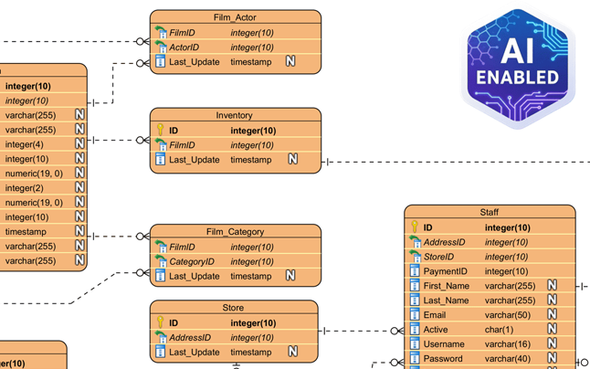
Ten model pełni rolę projektu budowy schematu bazy danych w konkretnym systemie DBMS. Rozwija model logiczny, przypisując konkretne typy danych, długości i ograniczenia (np. varchar(255), int, lub nullable).
Poziom szczegółowości
Fizyczny ERD jest bardzo szczegółowy. Definiuje dokładne Główne klucze (PK) i Klucze obce (FK) w celu ścisłego zapewnienia relacji. Ponadto musi uwzględnić specyficzne zasady nazewnictwa, słowa kluczowe zarezerwowane oraz ograniczenia dotyczące docelowego systemu zarządzania bazami danych.
Analiza porównawcza modeli ERD
Aby podsumować różnice między tymi poziomami architektury, poniższa tabela przedstawia cechy typowo obsługiwane przez różne modele:
| Cecha | Koncepcyjny | Logiczny | Fizyczny |
|---|---|---|---|
| Nazwy encji | Tak | Tak | Tak |
| Relacje | Tak | Tak | Tak |
| Kolumny/Attrybuty | Opcjonalnie/Brak | Tak | Tak |
| Typy danych | Nie | Opcjonalnie | Tak |
| Klucze główne | Nie | Tak | Tak |
| Klucze obce | Nie | Tak | Tak |
Optymalizacja projektowania za pomocą Visual Paradigm i AI
Tworzenie tych modeli ręcznie i zapewnienie ich spójności może być pracochłonne. Nowoczesne narzędzia takie jakVisual Paradigm wykorzystują automatyzację i sztuczną inteligencję, aby ułatwić przejście między tymi poziomami dojrzałości.
Przekształcanie modeli i śledzenie
Visual Paradigm oferujeModel Transitor, narzędzie zaprojektowane dowyprowadzenia modelu logicznego bezpośrednio z modelu koncepcyjnego, a następnie model fizyczny z modelu logicznego. Ten proces utrzymujeautomatyczne śledzenie, zapewniając, że zmiany w widoku biznesowym są poprawnie odzwierciedlone w technicznym projekcie.
Generowanie z wykorzystaniem AI
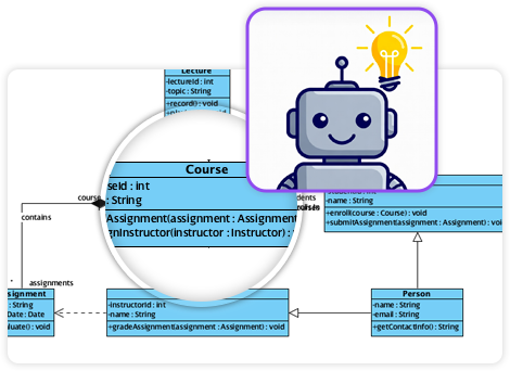
Zaawansowane funkcje obejmująmożliwości AI które mogą natychmiast tworzyć profesjonalne diagramy ER z opisów tekstowych. AI automatycznie wywnioskowuje encje i ograniczenia kluczy obcych, znacznie redukując czas potrzebny na ręczne ustawienie.

Synchronizacja dwukierunkowa
Kluczowe jest to, że platforma obsługujeprzekształcanie dwukierunkowe. Zapewnia to, że projekt wizualny i implementacja fizyczna pozostają zsynchronizowane, zapobiegając częstemu problemowi, gdy dokumentacja odchodzi od rzeczywistej bazy kodu.
-
Kompleksowa analiza DBModeler AI do projektowania schematów: szczegółowa analiza, jak DBModeler AI przekształca projektowanie schematów bazy danych za pomocą automatyzacji i inteligencji.
-
DBModeler AI: inteligentne narzędzie do modelowania baz danych: uzyskaj dostęp do narzędzia opartego na AI do automatycznego modelowania baz danych i generowania schematów w Visual Paradigm.
-
DBModeler AI: narzędzie do projektowania baz danych z wykorzystaniem AI z siedmiokrokowym przepływem pracy. Twórz modele dziedziny, diagramy ER, znormalizowane schematy i pełne raporty projektowe. Uruchom interaktywną platformę baz danych w przeglądarce, aby natychmiast przetestować zapytania.
-
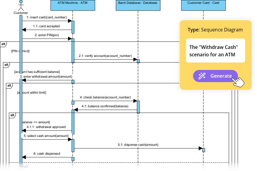
Analiza tekstowa z wykorzystaniem AI – automatyczne przekształcanie tekstu na modele wizualne: użyj AI do analizy dokumentów tekstowych i automatycznego generowania diagramów, takich jak UML, BPMN i ERD, aby przyspieszyć modelowanie i dokumentację.
-
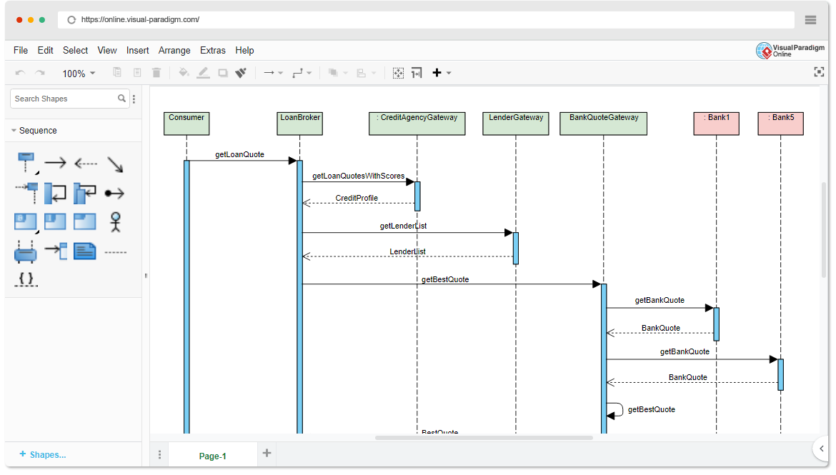
Narzędzie Visual Paradigm ERD – tworzenie diagramów encji-relacji online: Potężne narzędzie ERD oparte na przeglądarce, które pozwala użytkownikom na łatwe projektowanie i wizualizację schematów baz danych za pomocą intuicyjnych funkcji przeciągania i upuszczania.
-
Projektowanie bazy danych za pomocą narzędzi ERD – przewodnik Visual Paradigm: Kompletny przewodnik dotyczący używania narzędzi ERD do projektowania solidnych, skalowalnych baz danych zgodnie z najlepszymi praktykami modelowania danych i projektowania schematów.
-
Co to jest diagram encji-relacji (ERD)? – przewodnik Visual Paradigm: Głęboka analiza ERD, ich składników oraz znaczenia w projektowaniu baz danych i modelowaniu danych.
-
Bezpłatne narzędzie ERD – projektowanie baz danych online za pomocą Visual Paradigm: Dostęp do bezpłatnego narzędzia ERD online do tworzenia profesjonalnych diagramów encji-relacji bez instalacji i subskrypcji.
-
Jak rysować encje w narzędziu ERD Visual Paradigm: Krok po kroku przewodnik użytkownika dotyczący tworzenia i dostosowywania encji w narzędziu ERD Visual Paradigm w celu dokładnego modelowania baz danych.
-
Jak modelować bazę danych relacyjną za pomocą ERD – tutorial Visual Paradigm: Praktyczny tutorial pokazujący, jak używać ERD do modelowania baz danych relacyjnych od koncepcji po wdrożenie.