Mastering ERD: The 7-Step DB Modeler AI Workflow

In the evolving landscape of software engineering, bridging the gap between abstract business requirements and executable code is a critical challenge. 

ERD modeler

The DB Modeler AI workflow addresses this by implementing a guided 7-step journey. This structured process transforms an initial concept into a fully optimized, production-ready database schema, ensuring that technical execution aligns perfectly with business intent.
DBModeler AI showing ER diagram

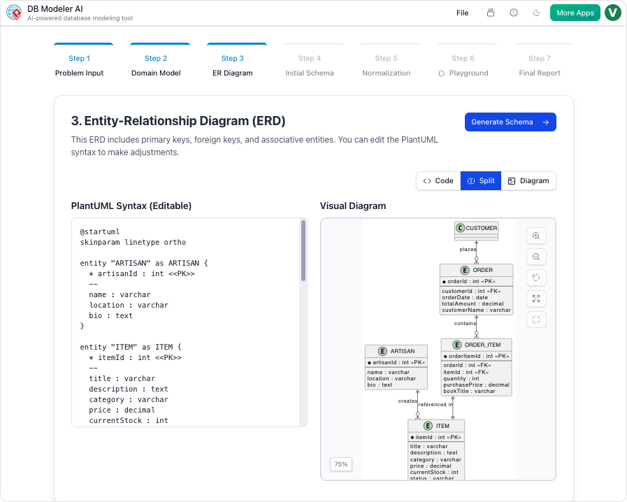
The Conceptual Phase: From Text to Visuals

The first stage of the workflow focuses on interpreting user intent and establishing a high-level visual representation of the data structure.

Step 1: Problem Input (Conceptual Input)

The journey begins with the user describing their application or project in plain English. Unlike traditional tools that require immediate technical syntax, DB Modeler AI allows for natural language input. The AI interprets this intent and expands it into comprehensive technical requirements. This step provides the necessary context for identifying core entities and business rules, ensuring that no critical data point is overlooked during the initial scoping.

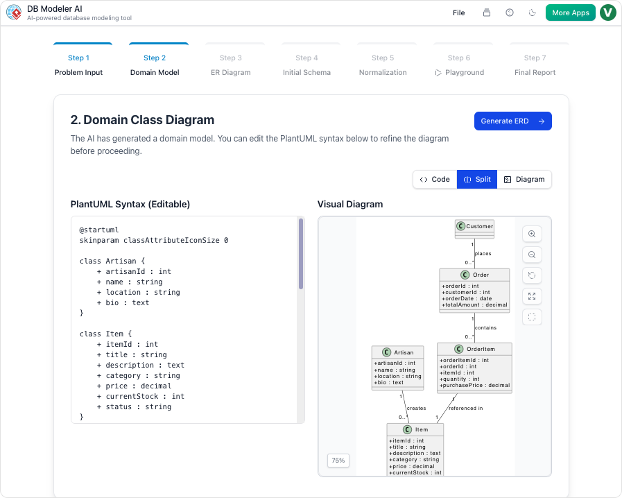
Step 2: Domain Class Diagram (Conceptual Modeling)

Once the requirements are established, the AI translates the textual data into a high-level visual blueprint known as a Domain Model Diagram. This diagram is rendered using editable PlantUML syntax, offering a flexible environment where users can visualize high-level objects and their attributes. This step is crucial for refining the scope of the database before committing to specific relationships or keys.

The Logical and Physical Design Phase

Moving beyond concepts, the workflow transitions into strict database logic and executable code generation.

Step 3: ER Diagram (Logical Modeling)

In this pivotal step, the tool converts the conceptual domain model into a database-specific Entity-Relationship Diagram (ERD). The AI automatically handles the complexity of defining essential database components. This includes the assignment of Primary Keys (PKs) and Foreign Keys (FKs), as well as the determination of cardinalities such as 1:1, 1:N, or M:N relationships. This transforms the abstract model into a logically sound database structure.

Step 4: Initial Schema Generation (Physical Code Generation)

With the logical model validated, the workflow proceeds to the physical layer. The refined ERD is translated into executable PostgreSQL-compatible SQL DDL statements. This automated process generates the code for all necessary tables, columns, and constraints directly derived from the visual model, eliminating the manual effort typically associated with writing Data Definition Language scripts.

Optimization, Validation, and Documentation

The final phases of the workflow ensure the database is efficient, tested, and well-documented for handover.

Step 5: Intelligent Normalization (Schema Optimization)

A standout feature of the DB Modeler AI workflow is its focus on efficiency. The AI progressively optimizes the schema by advancing it through the First (1NF), Second (2NF), and Third Normal Forms (3NF). Crucially, the tool provides educational rationales for every modification. This helps users understand how data redundancy is eliminated and how data integrity is ensured, turning the optimization process into a learning opportunity.

Step 6: Interactive Playground (Validation & Testing)

Before deployment, verification is essential. Users can experiment with their finalized schema in a live, in-browser SQL client. To facilitate immediate testing, the environment is automatically seeded with realistic, AI-generated sample data. This allows users to run custom queries and verify performance metrics in a sandbox environment effectively simulating real-world usage.

Step 7: Final Report and Export (Documentation)

The conclusion of the workflow is the generation of a professional Final Design Report. Typically formatted in Markdown, this report summarizes the entire design lifecycle. Users can export all diagrams, documentation, and SQL scripts as a polished PDF or JSON package, ready for project hand-off, team review, or long-term archiving.

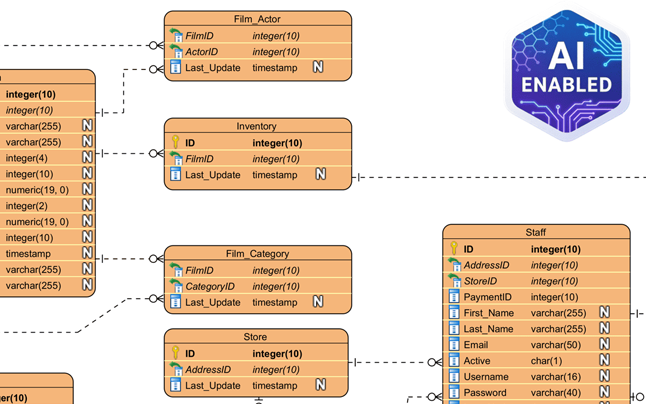
More ERD Examples Generated by Visual Paradigm AI

Understanding the Process: The Car Factory Analogy

To better understand the distinct value of each step, it is helpful to visualize the workflow as building a custom car in an automated factory. The following table maps the database engineering steps to this manufacturing analogy:

Workflow Step Database Action Car Factory Analogy
Step 1 Problem Input Your initial description of the car you want.
Step 2 Domain Class Diagram The artist’s sketch of the car’s look.
Step 3 ER Diagram The mechanical blueprint of how parts connect.
Step 4 Initial Schema Generation The actual manufacturing code for the machines.
Step 5 Intelligent Normalization Fine-tuning the engine for maximum efficiency.
Step 6 Interactive Playground A test drive on a virtual track with simulated passengers.
Step 7 Final Report and Export The final owner’s manual and the keys to the vehicle.

Visual Paradigm AI Tools Compared: DB Modeler AI vs. AI Chatbot

Introduction to Visual Paradigm’s AI Ecosystem

In the rapidly evolving landscape of system design and database management, the integration of Artificial Intelligence has become a pivotal factor for efficiency. 

Visual Paradigm AI Chatbot for Visual Modeling

Within the Visual Paradigm ecosystem, two tools stand out: the DB Modeler AI and the AI Chatbot. While both leverage generative capabilities to assist developers and architects, they are distinct yet interconnected instruments designed for specific phases of the design lifecycle.

DBModeler AI showing ER diagram

Understanding the nuance between these tools is critical for teams looking to optimize their workflow. While they share a foundation in AI, they differ significantly in their primary goals, structural workflows, and technical depth. This guide explores those differences to help you select the right tool for your project needs.

Primary Differences at a Glance

Before diving into the technical specifications, it is helpful to visualize the core distinctions between the two platforms. The following table outlines how each tool approaches goals, structure, and testing.

Feature DB Modeler AI AI Chatbot
Primary Goal Creating fully normalized, production-ready SQL schemas. Rapid diagram generation and conversational refinement.
Structure A rigid, guided 7-step technical workflow. An open-ended natural language conversation.
Normalization Automated progression from 1NF to 3NF with educational rationales. Focuses on visual structure rather than technical optimization.
Testing Features an interactive SQL playground with AI-generated sample data. Primarily for visual modeling and analysis; no live testing environment.
Versatility Specialized strictly for database design and implementation. Supports a vast universe of diagrams, including UML, SysML, ArchiMate, and business matrices.

DB Modeler AI: The End-to-End Specialist

The DB Modeler AI functions as a specialized web application designed to bridge the gap between abstract business requirements and executable database code. It is engineered for precision and architectural maturity.

The 7-Step Guided Journey

Unlike general-purpose tools, the DB Modeler AI enforces a structured approach. Its most notable feature is a 7-step guided journey that safeguards the integrity of the database design. This workflow ensures that users do not skip critical design phases, leading to a more robust final product.

Stepwise Normalization

One of the most complex tasks in database design is normalization—the process of organizing data to reduce redundancy and improve data integrity. DB Modeler AI automates this often error-prone task. It systematically optimizes a schema from First Normal Form (1NF) up to Third Normal Form (3NF). Uniquely, it provides educational rationales for its decisions, allowing users to understand why a table was split or a relationship modified.

Live Validation and Production Output

The tool goes beyond drawing. It features a Live Validation environment where users can launch an in-browser database. This allows for the immediate execution of DDL (Data Definition Language) and DML (Data Manipulation Language) queries against AI-seeded sample data. Once the design is validated, the system generates specific PostgreSQL-compatible SQL DDL statements, derived directly from the refined Entity-Relationship (ER) diagrams, making the output ready for deployment.

AI Chatbot: The Conversational Co-Pilot

In contrast to the rigid structure of the DB Modeler, the AI Chatbot acts as a broader, cloud-based assistant intended for general visual modeling. It is the tool of choice for rapid prototyping and broad system conceptualization.

Interactive Refinement

The AI Chatbot shines in its ability to interpret natural language commands for visual manipulation. Users can “talk” to their diagrams to facilitate changes that would traditionally require manual dragging and dropping. For example, a user might issue a command like “Rename Customer to Buyer” or “Add a relationship between Order and Inventory,” and the chatbot executes these visual refactors instantly.

Analytical Insights and Best Practices

Beyond generation, the AI Chatbot serves as an analytical engine. Users can query the chatbot regarding the model itself, asking questions such as “What are the main use cases in this diagram?” or requesting design best practices relevant to the current diagram type. This feature turns the tool into a consultant that reviews work in real-time.

Seamless Integration

The AI Chatbot is designed to fit into a wider ecosystem. It is available in the cloud and integrates directly into the Visual Paradigm Desktop environment. This interoperability allows users to generate diagrams via conversation and then import them into the desktop client for granular, manual modeling.

Integration and Use Case Recommendations

While distinct, these tools are often integrated in practice. For instance, the AI Chatbot is frequently utilized within the DB Modeler AI workflow to help users refine specific diagrammatic elements or answer architectural questions during the design process.

When to Use DB Modeler AI

  • Start here when initiating a new database project.
  • Use this tool when the requirement is a technically sound, normalized schema.
  • Choose this for projects requiring immediate SQL generation and data testing capabilities.

When to Use the AI Chatbot

  • Start here to quickly prototype system views.
  • Use this tool for non-database diagrams, such as UML, SysML, or ArchiMate.
  • Choose this for refining existing models through simple natural language commands without strict structural enforcement.

Analogy for Understanding

To summarize the relationship between these two powerful tools, consider a construction analogy:

The DB Modeler AI is comparable to sophisticated architectural software used by structural engineers. It calculates stress loads, blueprints every pipe, and ensures the building meets legal codes and stands upright physically. It is rigid, precise, and output-oriented.

The AI Chatbot is like an expert consultant standing next to you at the drafting table. You can ask them to “move that wall” or “draw a quick sketch of the lobby,” and they do it instantly based on your description. However, while they provide excellent visual guidance and advice, they are not necessarily running the deep structural engineering simulations required for the final blueprint.

Comprehensive Guide to Entity Relationship Diagrams (ERDs) and AI-Powered Design

In the complex world of software engineering and data management, the Entity Relationship Diagram (ERD) stands as a critical structural tool. Much like a blueprint is essential for architects to construct a safe building, an ERD allows database architects to plan, visualize, and maintain intricate data systems. This guide explores the fundamental concepts of ERDs, the stages of their development, and how modern Generative AI tools like Visual Paradigm are revolutionizing the design process.

Entity relationship diagram

1. Key Concepts of Entity Relationship Diagrams

To effectively design a database, one must first understand the core building blocks of an ERD. These diagrams map out the “nouns” of a system and the logical connections between them.

  • Entities: These represent the definable objects or concepts within a system—typically the nouns. Examples include a Student, a Product, or a Transaction. In standard visualizations, entities are depicted as rectangles.
  • Attributes (Columns): These are the specific properties that describe an entity. For a student, attributes might include names or ID numbers; for items, they could include price or SKU. These attributes are assigned specific data types, such as varchar for strings or int for integers.
  • Relationships: A crucial component that signifies how entities interact. For instance, a relationship exists when a “Student” enrolls in a “Course.”
  • Cardinality: This defines the numerical nature of the relationship between entities. Common cardinalities include one-to-one (1:1), one-to-many (1:N), and many-to-many (M:N).
  • Primary Key (PK) & Foreign Key (FK): A Primary Key is a unique identifier for a record, ensuring no duplicates exist. A Foreign Key is a reference used to link one table to the Primary Key of another, establishing the relationship.
  • Notations: Standardized visual languages are used to draw these diagrams. Chen Notation, for example, uses rectangles for entities, ovals for attributes, and diamonds for relationships.

2. Levels of Abstraction in Database Design

Creating a database is rarely a one-step process. ERDs are typically developed through three stages of “architectural maturity,” moving from abstract ideas to technical specifics.

Sync. between ER models

Conceptual ERD

This is the highest-level view, focusing on business objects and their relationships without getting bogged down in technical details. It is primarily used for requirements gathering and communication with non-technical stakeholders.

Logical ERD

At this stage, the design becomes more detailed. Attributes are explicitly defined, and keys are established. However, the model remains independent of any specific database technology (e.g., it doesn’t matter yet if you use MySQL or Oracle).

Physical ERD

This is the final technical blueprint tailored for a specific Database Management System (DBMS). It defines exact data types, column lengths, constraints, and indexing strategies required for implementation.

3. Accelerating Design with Visual Paradigm AI

Traditional database design can be manual and error-prone. The Visual Paradigm AI ERD tool integrates generative AI to automate complex parts of the lifecycle, transforming how engineers approach data modeling.

  • Instant Text-to-ERD: Users can describe requirements in plain English, and the AI instantly generates a structurally sound ERD complete with entities and relationships.
  • Conversational Editing: Through an AI Chatbot, designers can refine diagrams verbally. Commands like “Add payment gateway” or “Rename Customer to Buyer” are executed immediately without manual drawing.
  • Intelligent Normalization: One of the most difficult tasks in design is normalization. The tool automates optimization from 1NF to 3NF, providing educational rationales for the structural changes it makes.
  • Live Validation & Playground: The tool generates SQL DDL statements and creates an in-browser “Playground.” It seeds this environment with realistic sample data, allowing developers to test their design via queries immediately.
  • Multi-Language Support: To support global teams, the AI can generate diagrams and documentation in over 40 languages.

4. Specialized AI vs. General LLMs

While general Large Language Models (LLMs) can write text about databases, specialized tools like Visual Paradigm AI offer an engineering-grade environment.

Feature Visual Paradigm AI General AI LLM
Model Traceability Automatically keeps Conceptual, Logical, and Physical models in sync. Provides static text/code; no link between different abstraction levels.
Standards Compliance Ensures “textbook-perfect” notation (e.g., Chen or Crow’s Foot). May generate inconsistent or non-standard visual descriptions.
Engineering Integration Directly generates DDL/SQL scripts and patches existing databases. Limited to generating text-based SQL; requires manual implementation.
Live Testing Features an Interactive SQL Playground with AI-seeded data. Cannot host a “live” database environment for immediate query testing.
Visual Refinement Uses “Smart Layout” and conversational commands to arrange shapes. Cannot interact with or “clean up” a professional modeling canvas.

Summary: The Architect vs. The Friend

To understand the difference between using a general AI chatbot and a specialized ERD tool, consider this analogy: Using a general LLM for database design is like having a knowledgeable friend describe a house to you. They can tell you where the rooms should go, but they cannot give you a blueprint that the city will approve.

DBModeler AI showing domain class diagram

In contrast, using the Visual Paradigm AI tool is like hiring a certified architect and an automated builder. They draw the legal blueprints, ensure the infrastructure meets code (normalization), and build a small-scale model you can actually walk through (SQL playground) to verify functionality before the real construction begins. By bridging the gap between natural language and production-ready code, specialized AI ensures data integrity and drastically reduces architectural debt.

Why Natural Language Matters in Software Design

How plain English brings teams closer — and how AI turns it into structured diagrams

Software design has long relied on specialized notations, diagrams, and technical documentation. But before any of that exists, ideas usually start as simple conversations: “The user logs in and views their dashboard.” The challenge is that translating those everyday descriptions into formal models often introduces confusion or inconsistency.

Natural language — when used effectively — helps bridge that gap, enabling smoother collaboration and faster understanding across diverse teams. And now, with the help of AI, plain English can be instantly transformed into formal, visual representations.

The Language Barrier in Software Design

Designers, developers, and business stakeholders often speak in different “languages.”

  • Developers think in terms of classes, components, and APIs.
  • Analysts write requirements and use cases.
  • Clients describe goals and user experiences in plain terms.

Without a shared language, communication becomes fragmented. Technical precision is important, but it can also alienate non-technical members who need to understand system behavior. Natural language provides that bridge — an accessible, neutral medium that keeps everyone aligned before diving into structure.

From Plain Description to Clear Design

Using natural language to describe systems encourages clarity. When team members must explain how something works in words, they often uncover missing steps, unclear ownership, or hidden dependencies.

For instance, describing a process as:

“A customer places an order, the system verifies payment, and the warehouse ships the item.”

Already suggests a flow, roles, and order of actions. But turning that into a formal diagram — such as a use case or sequence model — requires interpretation. That is where AI-driven tools step in.

Why Natural Language Matters in Software Design

How AI Interprets Natural Language

Modern AI modeling assistants, such as the one in Visual Paradigm Online, use natural language processing to analyze plain descriptions and generate corresponding diagrams. You simply describe the process in your own words, and the AI identifies key actors, relationships, and interactions.

For example:

  • “User logs in” → creates an actor and use case.
  • “System sends confirmation email” → adds an interaction.
  • “Manager reviews report” → introduces another role and process flow.

In seconds, you can see your text transformed into a visual model that follows standard notation. It makes technical structure visible, yet accessible to everyone who contributed to the initial description.

Improving Collaboration Through Shared Understanding

When natural language serves as the starting point, teams communicate more naturally and make fewer assumptions. AI supports this by acting as a translator between human intent and formal structure.

The results are clear:

  • Clarity: Everyone understands the system without needing to read complex specifications.
  • Consistency: The AI ensures relationships and elements are logically connected.
  • Speed: The process from idea to visualization is almost instant.
  • Inclusivity: Stakeholders with different technical levels can still participate meaningfully.

Another advantage of working with an AI modeling assistant is that the entire chat history can be shared. Each prompt and response documents how the model evolved — from initial ideas to refined diagrams. This shared record makes it easier for teammates to review past discussions, understand design rationale, and continue collaboration without losing context.

Instead of being a tool reserved for technical experts, diagram creation becomes a transparent, shared process where everyone can contribute and stay aligned.

The Power of Conversation in Modern Design

Software design is becoming more conversational. Instead of filling templates or manually creating diagrams, teams can now describe ideas naturally and let AI assist in structuring them. This conversational approach reduces friction, encourages collaboration, and helps teams reach consensus faster.

In platforms like Visual Paradigm’s AI Chatbot, that concept comes to life. It listens, understands, and models — turning your sentences into structured, standards-compliant visuals.

From Words to Diagrams, and Ideas to Systems

Natural language is not a replacement for formal modeling — it is the foundation. By expressing ideas clearly in words and allowing AI to handle translation into visual form, teams gain both understanding and precision.

Software design is, at its core, a communication process. And with the support of AI-powered tools, plain English has never been more powerful in bringing people and systems together.

Integrating AI Diagram Generation into Your Daily Workflow

Modern projects demand clarity, speed, and collaboration — but turning ideas into visuals often takes longer than expected. Whether you are documenting a process, explaining a concept, or planning a new system, creating diagrams can consume valuable time. This is where AI-powered tools like the Visual Paradigm Online AI Chatbot redefine the workflow.

By understanding natural language and generating ready-to-edit diagrams, the chatbot transforms how you work — from concept to completion.

A Smarter Way to Start Your Day

Instead of beginning with a blank canvas, you can start with a conversation. Describe your idea or workflow in plain language, and let AI create the first version for you.

For example:

  • “Generate a UML Class Diagram for a library management system.”
  • “Show a workflow of project approval with manager and admin roles.”

These prompts instantly produce structured diagrams that you can refine in the Visual Paradigm Online Diagram Editor.

Integrating AI Diagram Generation into Your Daily Workflow

Bringing AI into Documentation

Documentation often involves explaining complex systems or processes. AI diagram generation simplifies this by turning written descriptions into visuals that enhance understanding.

You can use it to:

  • Illustrate system design directly from your written notes or reports.
  • Generate quick visuals for documentation updates without redrawing manually.
  • Maintain consistency across diagrams by using AI-generated templates.

This makes maintaining technical or business documentation faster and more consistent.

Supporting Teaching and Learning

Educators and trainers can also integrate AI-generated diagrams into their lessons. By turning abstract ideas into visual examples within seconds, AI helps make learning more interactive and effective.

For instance:

  • Teachers can demonstrate how a UML sequence works by simply typing a system description.
  • Students can explore how changing a single prompt affects the resulting diagram — learning structure through experimentation.
  • Training materials can be enriched with automatically generated visuals that match the lesson content.

This hands-on approach bridges theoretical learning and practical application.

Accelerating Design Planning

When planning systems or workflows, AI gives teams a faster way to visualize ideas before finalizing them. You can brainstorm freely, test different structures, and iterate quickly without worrying about diagram formatting.

Common scenarios include:

  • Project planning: Visualize team responsibilities and approval processes.
  • Software design: Draft system structures and relationships for discussion.
  • Process improvement: Identify inefficiencies by mapping workflows through quick AI drafts.

Once the base structure is ready, it can be fine-tuned collaboratively in VP Online.

Making AI Part of Your Routine

Integrating AI into your workflow is not about replacing creativity — it is about removing barriers. By automating structure creation, AI lets you focus on logic, flow, and communication.

In your daily work, that means:

  • Fewer hours spent drawing manually.
  • Clearer diagrams created directly from your own language.
  • Faster turnaround for documentation, lessons, and design plans.

A More Efficient Way to Work

The Visual Paradigm Online AI Chatbot makes diagramming an integrated part of your daily routine — quick, flexible, and intelligent. Whether you are a teacher, analyst, or designer, you can turn everyday ideas into professional visuals with a simple conversation.

AI vs. Manual Diagramming: Which Fits Your Workflow?

For years, creating diagrams meant manually dragging shapes, aligning connectors, and labeling components. It was precise but time-consuming.
Now, AI-powered tools like the Visual Paradigm Online AI Chatbot have transformed how diagrams are made — turning text prompts into complete UML, BPMN, or flow diagrams in seconds.

But which method fits your workflow better: AI or manual diagramming? Let us explore the pros and cons of each, and how combining both delivers optimal results.

Manual Diagramming: Total Control with More Effort

Manual diagramming has long been the standard approach for professionals. It gives full creative freedom — every element, layout, and connection is crafted exactly as intended.

Advantages:

  • Full design control: You decide the layout, naming, and visual details.
  • Better conceptual understanding: Drawing shapes manually deepens comprehension of system logic.
  • High customization: Ideal for refining presentations and meeting specific visual standards.

Challenges:

  • Time-consuming: Complex diagrams can take hours to perfect.
  • Repetitive adjustments: Minor changes may require extensive rearrangement.
  • Steep learning curve: Beginners often struggle with modeling notation and best practices.

Manual diagramming remains valuable for experienced modelers who need accuracy, but it demands more time and effort.

AI Diagramming: Speed and Simplicity at Scale

AI-driven diagramming tools like Visual Paradigm Online’s AI Chatbot use natural language to create diagrams automatically.
You simply describe what you need — for example:

“Create a UML Class Diagram for an online store with classes Customer, Order, and Product.”

Within seconds, the tool generates a structured, ready-to-edit diagram.

AI vs. Manual Diagramming: Which Fits Your Workflow?

Advantages:

  • Instant results: Generate complete diagrams in moments.
  • No modeling expertise required: AI handles syntax and structure automatically.
  • Great for brainstorming: Quickly visualize early-stage ideas or compare multiple versions.

Challenges:

  • Less control over layout: AI focuses on accuracy, not presentation aesthetics.
  • Limited creative fine-tuning: Some customization still requires manual editing.
  • Dependent on prompt clarity: Results vary with how well the request is described.

AI diagramming excels in speed, accessibility, and automation — especially useful for quick iterations or concept validation.

Finding the Balance: Why You Need Both

Rather than choosing one approach, modern workflows benefit most from AI-assisted manual editing.
The Visual Paradigm Online AI Chatbot integrates both worlds in a single environment:

Start with AI generation — instantly create your base diagram from text.

  • Ask AI for adjustments or explanations — such as “Add an inheritance relationship” or “Explain this interaction.”
  • Switch to manual editing — refine, reposition, and style elements directly in the editor.

This hybrid approach saves time while preserving full control, allowing you to stay productive from brainstorming to final documentation.

Real-World Use Cases

  • Software Designers: Use AI to draft UML diagrams, then fine-tune manually for precise system documentation.
  • Business Analysts: Generate BPMN or flowcharts for meetings, then refine key steps for clarity.
  • Students & Educators: Learn UML or process modeling faster with real-time examples and feedback.

Each use case benefits from AI efficiency without losing manual precision — a balance ideal for professional and educational environments alike.

The Best of Both Worlds with Visual Paradigm Online

Visual Paradigm Online provides an integrated modeling workspace that supports AI-assisted creation and manual refinement seamlessly.
You can:

  1. Generate diagrams from natural-language prompts.
  2. Request AI-based explanations or improvements.
  3. Edit every element manually in the visual editor.
  4. Save and share your work in the cloud instantly.

By merging automation and human creativity, it ensures your workflow is both fast and flexible — without sacrificing quality or clarity.

Conclusion

AI and manual diagramming each have unique strengths. Manual design offers precision and control; AI provides speed and simplicity.
The Visual Paradigm Online AI Chatbot combines both, allowing you to start fast, refine easily, and deliver professional results in less time.
Whether you are designing systems, mapping processes, or learning UML, this balance ensures your diagrams truly fit your workflow.

Share the Blueprint, Not the File: Collaborating on Architecture with Shareable AI Chat History

In complex projects, sharing a diagram as a static file (PNG, PDF) is fundamentally insufficient. It provides the final result but omits the crucial context: why the diagram was created that way, who requested the changes, and *what* alternatives were considered. This forces stakeholders to initiate tedious email chains and ask repetitive questions, delaying crucial sign-offs and increasing the risk of misinterpretation.Effective collaboration requires sharing the rationale and evolution of the model, not just the final image. The design process—the conversation itself—is as important as the artifact.

Visual Paradigm’s AI Chatbot solves this by treating the entire design conversation as the definitive artifact, making it perfectly suited for modern, transparent, and asynchronous collaboration.

Share the Evolution, Not Just the Endpoint

The AI enables two powerful collaboration features that redefine how teams work with models:

  1. Persistent Chat History: Every interaction—the initial prompt, the generated diagram (UML, C4, ArchiMate), every subsequent touch-up operation (e.g., “add container,” “rename system”), and every AI answer—is automatically saved in a persistent **chat history**. This history is the ultimate source of truth for design decisions.
  2. Shareable URL: You can **share a chat session with others via a URL**. When a stakeholder opens the link, they see the entire transcript. They can review the design evolution from the high-level description to the final, detailed **UML Class Diagram** or **C4 Deployment Diagram**.

This creates a complete, contextual audit trail for the project, drastically reducing back-and-forth communication and ensuring all stakeholders understand the *why* behind the architecture.

Share the Blueprint, Not the File: Collaborating on Architecture with Shareable AI Chat History

Enhanced Review and Accountability

This dynamic sharing capability is invaluable for several key team activities where transparency is critical:

  • Stakeholder Review: Instead of a static presentation, send the chat history. Stakeholders can review the evolution of the model and immediately see the AI’s **suggested follow-up questions**, guiding them to consider the deeper implications of the design rather than just commenting on aesthetics.
  • Onboarding and Training: New team members can review the chat history for key models to quickly grasp the project’s architecture and the decisions that shaped it. The history acts as a living knowledge base, explaining complex concepts in context.
  • Consulting and Client Work: Consultants can use the shareable link as a transparent record of all modeling work, providing clients with an undeniable, clear record of the design process, decision rationale, and model compliance checks.
  • Auditability: The ability to track the exact prompt that led to a design change provides an indispensable record for regulatory compliance or post-incident technical review.

Collaboration Beyond the Diagram

The AI ensures all aspects of project communication are covered within the collaborative chat session.

  • Integrated Documentation: Before sharing, you can ask the AI to **generate a narrative report** summarizing the model. This report and the generating prompt are also stored in the shareable history, providing a perfect blend of visual and textual documentation.
  • Standards Adherence: Because the AI is expertly trained on major standards, the shared models adhere to clear compliance rules, making it easier for distributed teams to collaborate effectively without constant manual validation.
  • Modeling Continuity: Even after a conversation is shared, the original user can **import the model into Visual Paradigm** for professional version control and repository management, maintaining the design continuity from initial collaborative conversation to final implementation.

Stop sending outdated PDFs and static images. Start sharing the living, collaborative blueprint of your design process. The future of architectural review is conversational and transparent.

Facilitate transparent architectural collaboration today at chat.visual-paradigm.com.