Czy jesteś gotowy, aby przeobrazić swój proces projektowania bazy danych? Tworzenie profesjonalnego Diagram relacji encjizajmowało godziny ręcznego przesuwania kształtów i dokładnego rysowania połączeń. Nie więcej! Dzięki narzędziu do tworzenia diagramów ERD z wykorzystaniem AI zintegrowanemu bezpośrednio w Visual Paradigm, możesz wygenerować diagram relacji encjimodele na podstawie prostych opisów tekstowych w zaledwie kilka sekund. Niezależnie od tego, czy budujesz złożony system biblioteczny, czy system inwentarzowy dla sklepu z dużym ruchem, to łatwe w użyciu narzędzie do tworzenia diagramówwykorzystuje zaawansowaną inteligencję, by zająć się ciężką pracą, pozwalając Ci skupić się na architekturze najwyższego poziomu, a nie na ręcznym formatowaniu!
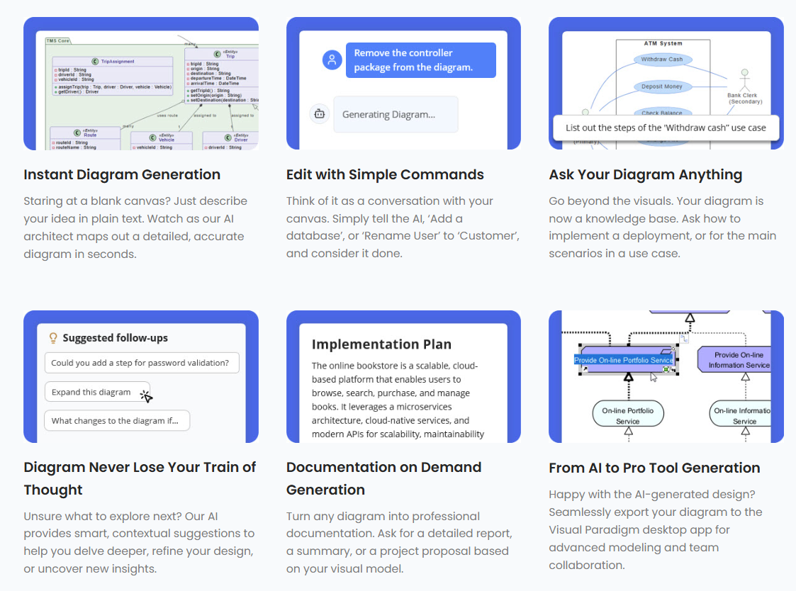
Kluczowe wnioski dotyczące modelowania z wykorzystaniem AI
-
Natychmiastowa transformacja modelu: Przekształć wymagania w języku naturalnym w dokładne schematy bazy danych.
-
Notacja zgodna z normami: Automatycznie używaj poprawnej notacji Crow’s Foot lub IDEF1X dla encji i relacji.
-
Szybka eksploracja: Testuj różne scenariusze architektoniczne, zmieniając tylko swój tekstowy prompt.
-
Pełna edytowalność: Każdy wygenerowany element jest obiektem natywnym Visual Paradigm, gotowym do ręcznej poprawki.
Podstawowy przepływ pracy: jak generować diagramy relacji encji za pomocą AI
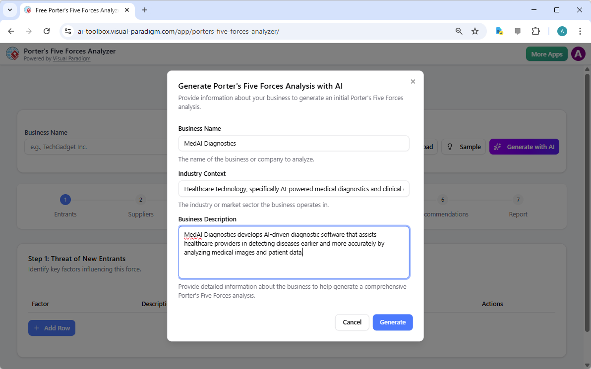
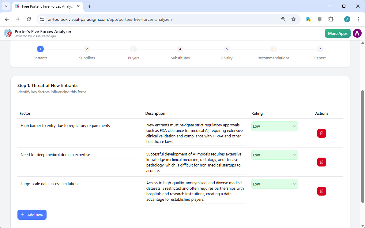
Droga do idealnego modelu bazy danych zaczyna się w solidnym środowisku Visual Paradigm Desktop. Aby rozpocząć czar, po prostu przejdź do głównego menu i wybierz Narzędzia > Generowanie diagramów z wykorzystaniem AI. Otwiera dedykowany portal, w którym Twoje opisy słowne są przekładane na szkice strukturalne. To idealny punkt wyjścia dla każdego inżyniera oprogramowania lub architekta danych, który ceni wydajność!
Gdy pojawi się okno generowania, zostaniesz przedstawiony interfejsu zoptymalizowanemu pod kątem maksymalnej produktywności. Najpierw upewnij się, że wybrałeś Diagram relacji encjiz rozwijanej listy Typu diagramu. Następnie wpisz swój opisowy prompt w pole Temat. W naszym przykładzie podaliśmy bardzo szczegółowe wymagania: „Diagram ERD do zarządzania biblioteką, który definiuje relacje między książkami, członkami i wypożyczeniami.” Ta jasność pozwala na profesjonalny oprogramowanie do rysowania diagramów z wykorzystaniem sztucznej inteligencji wywnioskować niezbędne encje, takie jak numery ISBN, daty terminowe i typy członkostwa, bez dodatkowych instrukcji!
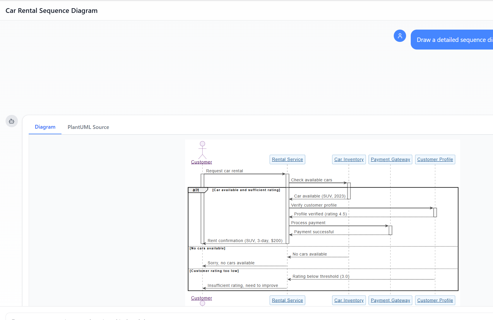
Analiza inteligentnego wyniku
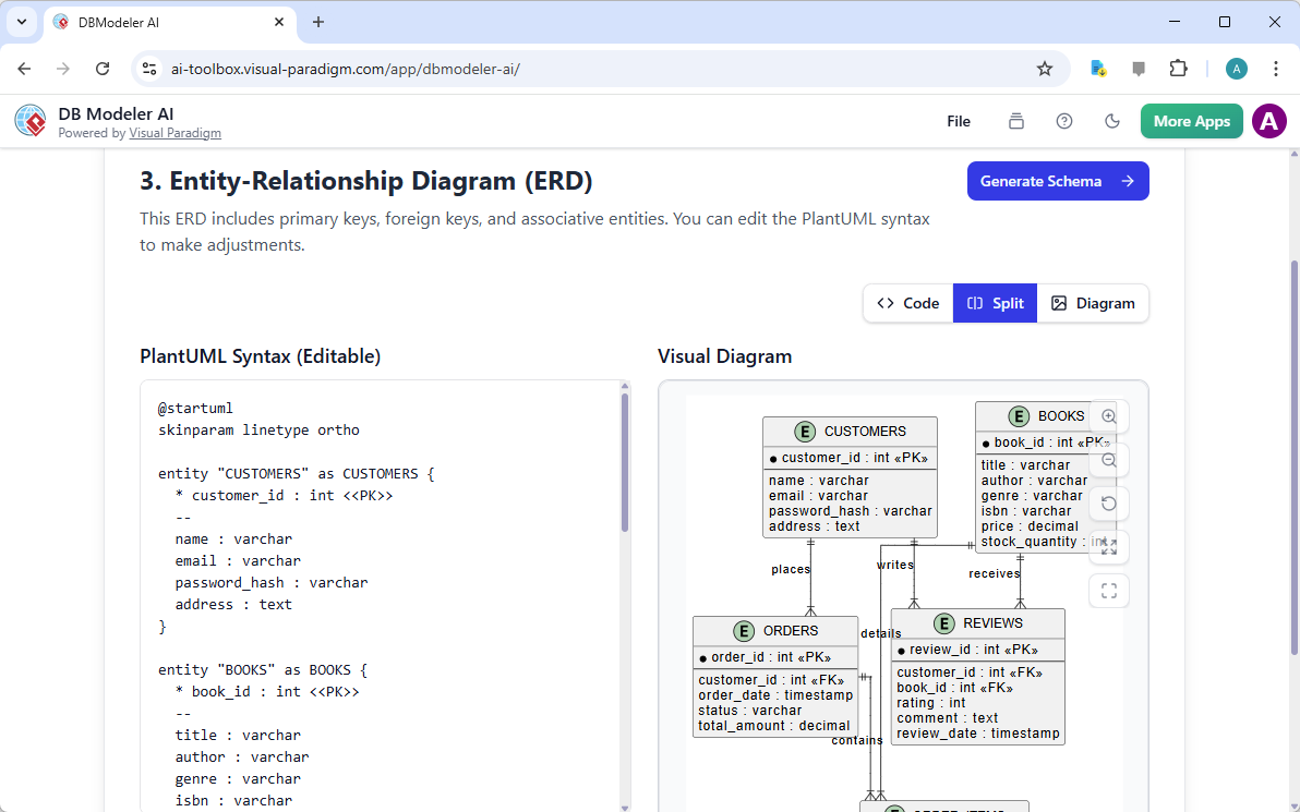
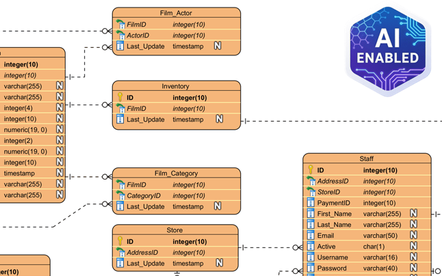
Po kliknięciu „OK”, narzędzie do projektowania z wykorzystaniem sztucznej inteligencji przeprowadza głęboką analizę Twojego tekstu i tworzy kompleksowy model. W naszym scenariuszu zarządzania biblioteką AI pomyślnie zidentyfikowało i utworzyło encje takie jak CatalogEntry, Book, BookCopy, Member i Loan. Nawet inteligentnie zaproponowało wspomagające tabele takie jak Fine, Payment, Staff i OverdueRecord aby zapewnić kompletną logikę systemu. Każdy klucz główny, klucz obcy i połączenie kardynalności jest precyzyjnie umieszczony, zapewniając solidną podstawę dla dokumentacji bazy danych.
Jednym z najpotężniejszych aspektów tej funkcji jest to, że wynik nie jest statycznym obrazem, ale pełnie zintegrowanym i edytowalnym modelem. Możesz natychmiast dokonać „dokładnych poprawek”, aby dostosować diagram do konkretnych potrzeb projektu. Niezależnie od tego, czy chcesz zmienić nazwę atrybutu, dodać nową encję lub zmodyfikować typ relacji – na przykład zmienić połączenie na relację jeden do jednego—intuicyjny interfejs pozwala na płynne ręczne dostosowania za pomocą katalogu zasobów i narzędzi edytora.
Wnioski: podnieś swoją strategię projektowania
Wybierając wygenerować diagram relacji encji modele za pomocą nowoczesnej sztucznej inteligencji Visual Paradigm, nie tylko oszczędzasz czas, ale również zapewnicasz, że Twoja dokumentacja odpowiada najlepszym praktykom branżowym już od pierwszego kliknięcia. To profesjonalne narzędzie do tworzenia diagramów ERD z wykorzystaniem sztucznej inteligencjimostkuję luki między wymaganiami koncepcyjnymi a wykonaniem technicznym, czyniąc je najlepszym łatwym w użyciu oprogramowaniem dla nowoczesnych zespołów deweloperskich. Doświadcz przyszłości modelowania wizualnego już dziś i pozwól, by Twoja kreatywność prowadziła drogę!
Gotowy na przekształcenie swojego toku pracy?
Odblokuj pełny potencjał swojego procesu projektowania, pobierając najnowszą wersję Visual Paradigm. Postępuj zgodnie z linkiem poniżej, aby rozpocząć pracę z najnowocześniejszym aplikacją do rysowania diagramów z wykorzystaniem sztucznej inteligencji.
Pobierz Visual Paradigm Desktop: https://www.visual-paradigm.com/download/
Linki powiązane
Diagramy encji-relacji (ERD) to podstawowe narzędzia do projektowania baz danych i modelowania danych, używane do wizualizacji statycznej struktury systemów informacyjnych poprzez definiowanieencji, atrybutów i ich interakcji. Visual Paradigm oferuje obszerny zestaw narzędzi ERD—dostępnych zarówno na komputerach stacjonarnych, jak i w chmurze—które wspierają różne standardy, w tymnotację Chen, aby ułatwić dokładny rozwój schematów. Nowoczesne ulepszenia platformy obejmują obecniefunkcje oparte na technologii AI które mogą natychmiast generować edytowalne diagramy ERD na podstawie opisów w języku naturalnym lub poprzezodwrotne inżynieriaistniejących baz danych, znacznie ułatwiającprzepływ implementacji.
-
Co to jest diagram encji-relacji (ERD)? – Przewodnik Visual Paradigm: Kompletny zasób obejmujący składniki, notację i znaczenie diagramów ERD w nowoczesnym modelowaniu baz danych.
-
Narzędzie ERD Visual Paradigm – tworzenie diagramów encji-relacji online: Szczegóły dotyczące potężnego edytora opartego na przeglądarce, zaprojektowanego do intuicyjnego projektowania złożonych schematów baz danych za pomocą przeciągania i upuszczania.
-
Jak modelować bazę danych relacyjną za pomocą ERD – tutorial Visual Paradigm: Praktyczny, krok po kroku tutorial prowadzący użytkowników od modelowania koncepcyjnego danych do finalnej implementacji.
-
Projektowanie baz danych za pomocą narzędzi ERD – przewodnik Visual Paradigm: Przegląda najlepsze praktyki budowania skalowalnych, wydajnych baz danych i synchronizacji modeli między różnymi etapami rozwoju.
-
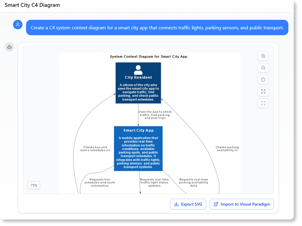
Nowe typy diagramów dodane do generatora diagramów opartego na AI: DFD i ERD: Informacje o najnowszych możliwościach AI, które pozwalają użytkownikom automatycznie tworzyć strukturalne diagramy ERD na podstawie prostych promptów tekstowych.
-
Uproszczenie modelowania encji-relacji za pomocą Visual Paradigm: szczegółowy przegląd sposobu skutecznego przejścia od początkowych koncepcji danych do implementacji za pomocą narzędzi modelowania wizualnego.