資料庫設計中架構成熟度的重要性
實體關係圖(ERD)是有效系統架構的骨幹。它們並非靜態的圖示,而是在三個不同的架構成熟度階段中逐步發展而成。架構成熟度。每個階段在資料庫設計生命週期中扮演著獨特的角色,服務對象從利益相關者到資料庫管理員不等。雖然三種層級都包含實體、屬性和關係,但它們在細節深度與技術專注度上存在顯著差異。
要真正理解這些模型的演進過程,使用建築類比會很有幫助。想像建造一棟房子:一個概念ERD是建築師最初的草圖,顯示房間(如廚房和客廳)的大致位置。而邏輯ERD是詳細的平面圖,明確標示尺寸與家具擺放位置,但尚未指定材料。最後,物理ERD則是工程圖紙,明確指定水管、電路佈線以及地基所使用的特定品牌混凝土。
1. 概念ERD:業務視角
這個概念ERD代表最高層次的抽象。它提供業務物件及其關係的戰略性視角,完全去除技術上的雜亂。
目的與重點
此模型主要用於需求收集以及呈現整體系統架構。其主要目標是促進技術團隊與非技術利益相關者之間的溝通。它著重於定義有哪些實體存在——例如「學生」、「產品」或「訂單」——而非這些實體將如何在資料庫表格中實現。
細節層級
概念模型通常缺乏技術限制。例如,多對多關係通常僅以關係形式呈現,而不涉及基數或關聯表格的複雜性。獨特的是,此層級可能使用泛化,例如將「三角形」定義為「形狀」的子類型,這是一個在後續物理實現中被抽象化的概念。
2. 邏輯ERD:詳細視角
隨著成熟度量表的下降,邏輯實體關係圖作為概念模型的增強版本,彌合了抽象業務需求與具體技術實現之間的差距。
目的與重點
邏輯模型將高階需求轉化為操作性和交易性實體。雖然它定義了明確的欄位每個實體的欄位,但仍然完全獨立於特定的資料庫管理系統(DBMS)在這個階段,最終資料庫是使用 Oracle、MySQL 或 SQL Server 並無差別。
細節層級
與概念模型不同,邏輯實體關係圖為每個實體包含屬性。然而,它不會進一步指定技術上的細節,例如資料類型(如整數與浮點數)或特定欄位長度。
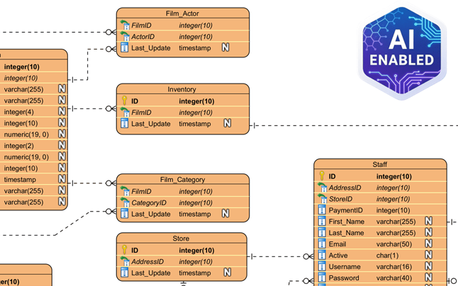
3. 物理實體關係圖:技術藍圖
這個物理實體關係圖代表關係型資料庫的最終、可執行的技術設計。這就是將被部署的資料結構。
目的與重點
此模型作為在特定資料庫管理系統中建立資料庫結構的藍圖。它透過指派特定的資料類型、長度與限制條件(例如varchar(255), int,或可為空值).
細節層級
物理實體關係圖非常詳細。它定義精確的主要鍵(PK)以及外鍵 (FK)以嚴格強制關係。此外,還必須考慮目標資料庫管理系統的特定命名慣例、保留字和限制。
ERD 模型的比較分析
總結這些架構層級之間的差異,下表概述了不同模型中通常支援的功能:
| 功能 | 概念 | 邏輯 | 物理 |
|---|---|---|---|
| 實體名稱 | 是 | 是 | 是 |
| 關係 | 是 | 是 | 是 |
| 欄位/屬性 | 可選/否 | 是 | 是 |
| 資料類型 | 否 | 可選 | 是 |
| 主鍵 | 否 | 是 | 是 |
| 外鍵 | 否 | 是 | 是 |
透過 Visual Paradigm 與人工智慧簡化設計
手動建立這些模型並確保它們保持一致可能非常耗時。現代工具如Visual Paradigm利用自動化與人工智慧,簡化這些成熟度層級之間的轉換。
模型轉換與可追溯性
Visual Paradigm 提供一個Model Transitor,一個專為從概念模型直接推導出邏輯模型,並進一步從邏輯模型推導出物理模型。此流程維持自動可追溯性,確保業務視圖中的變更能準確反映在技術藍圖中。
人工智慧驅動的生成
進階功能包括人工智慧功能可從文字描述中立即生成專業的實體關係圖。人工智慧會自動推斷實體與外鍵約束,大幅減少手動設定時間。

雙向同步
關鍵的是,該平台支援雙向轉換。這確保視覺設計與實際實現保持同步,避免常見的文件與實際程式碼庫脫節的問題。
-
DBModeler AI 資料庫結構設計全面評估:詳細分析 DBModeler AI 如何透過自動化與智慧化技術轉化資料庫結構設計。
-
DBModeler AI:智慧型資料庫建模工具:存取由人工智慧驅動的工具,於 Visual Paradigm 中自動進行資料庫建模與結構產生。
-
DBModeler AI:具備七步流程的人工智慧驅動資料庫設計工具。產生領域模型、實體關係圖、規範化結構與完整的設計報告。啟動即時瀏覽器資料庫沙盒,立即測試查詢。
-
人工智慧文字分析 – 自動將文字轉換為視覺化模型:使用人工智慧分析文字文件,自動產生 UML、BPMN 和 ERD 等圖表,以加速建模與文件編制。
-
Visual Paradigm ERD 工具 – 在線創建實體關係圖:一款強大的基於網絡的 ERD 工具,讓使用者能透過直覺的拖放功能輕鬆設計和視覺化資料庫結構。
-
使用 ERD 工具進行資料庫設計 – Visual Paradigm 指南:全面指南,介紹如何使用 ERD 工具以最佳實踐進行資料模型設計與結構設計,打造穩健且可擴展的資料庫。
-
什麼是實體關係圖(ERD)? – Visual Paradigm 指南:深入解釋 ERD 的構成要素及其在資料庫設計與資料模型中的重要性。
-
免費 ERD 工具 – 使用 Visual Paradigm 在線設計資料庫:免費在線使用 ERD 工具,無需安裝或訂閱,即可創建專業的實體關係圖。
-
如何在 Visual Paradigm ERD 中繪製實體:逐步使用者指南,介紹如何在 Visual Paradigm 的 ERD 工具中建立並自訂實體,以實現精確的資料庫建模。
-
如何使用 ERD 建立關係型資料庫 – Visual Paradigm 教學:實用教程,展示如何從概念到實現,利用 ERD 建立關係型資料庫。