


In modern software and systems design, visualizing processes is essential for clarity, collaboration, and documentation. OpenDocs, powered by Visual Paradigm, offers a powerful, AI-enhanced environment to model workflows using UML (Unified Modeling Language). This tutorial walks you through creating a UML Activity Diagram—the ideal choice for modeling business processes, system workflows, and control flows—step by step.
✅ Why Use UML Activity Diagrams in OpenDocs?
UML Activity Diagrams are specifically designed to represent:

-
The flow of control in a system.
-
Sequential and concurrent actions.
-
Decision points, loops, and parallel branches.
-
Real-world business processes such as customer onboarding, order fulfillment, or refund processing.
With OpenDocs, you can build these diagrams manually or leverage AI-powered generation to accelerate your workflow.
🛠️ Step-by-Step Guide: Creating a UML Activity Diagram in OpenDocs
Follow these steps to create a professional, interactive UML process diagram in OpenDocs.
Step 1: Open or Create a New Page
-
Launch the OpenDocs application.
-
Navigate to your project or click “New Page” from the sidebar.
-
Give your page a descriptive name, such as “Customer Refund Process”.
💡 Tip: Use clear, descriptive titles to improve document navigation and team collaboration.
Step 2: Access the Diagram Editor
-
In the top navigation bar, click the Insert button.
-
Select the Diagrams tab from the dropdown menu.
-
Choose Activity Diagram from the list of UML diagram types.
✅ This opens the Diagram Editor, where you can begin building your process model.
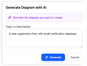
Step 3: Generate with AI (Optional but Powerful)
Use the AI-powered diagram generator to create a draft instantly based on your description.
-
Click Create with AI in the top-right corner of the editor.
-
Enter a clear prompt such as:
“Create an activity diagram for a customer refund process, including steps like refund request, verification, approval, and refund issuance.”
-
Click Generate.
The AI will:
-
Analyze your prompt.
-
Draft a structured diagram with actions, decisions, and flow.
-
Suggest appropriate UML symbols and layout.
🚀 This saves hours of manual work and provides a strong starting point for refinement.
Step 4: Manual Construction & Refinement
Even with AI assistance, manual editing ensures accuracy and alignment with your needs.
Add UML Symbols from the Palette
Drag and drop the following standard UML elements onto the canvas:
| Symbol | Purpose |
|---|---|
| Start Node (Circle with a dot) | Marks the beginning of the process. |
| Action (Rounded Rectangle) | Represents a step or task (e.g., “Receive Refund Request”). |
| Decision (Diamond) | Indicates a branching point (e.g., “Is request valid?”). |
| Merge (Diamond) | Combines multiple flows back into one. |
| End Node (Circle with a thick border) | Marks the end of the process. |
Connect the Steps
-
Use the Connector Tool (usually a line with an arrow) to link symbols.
-
Arrows show the flow of control from one action to the next.
-
For branching logic, draw arrows from the Decision diamond to multiple outcomes (e.g., “Yes” → “Approve”, “No” → “Reject”).
Edit and Customize Content
-
Double-click any shape to:
-
Rename the action (e.g., change “Action1” to “Verify Customer ID”).
-
Add descriptions or notes.
-
-
Use the Properties Panel to adjust colors, fonts, or add metadata.
✏️ Best Practice: Keep labels concise and action-oriented. Avoid vague terms like “Process Step 1.”
Step 5: Save and Embed the Diagram
Once your diagram is complete:
-
Click Save to preserve your work.
-
Click Close to exit the editor.
-
The diagram is automatically embedded into your OpenDocs page as an interactive component.
🔗 Interactive Features:
Hover over elements to see tooltips.
Click to edit directly in the document.
Export to PNG, PDF, or SVG for sharing.
📊 Common UML Diagrams for Modeling Processes
While Activity Diagrams are best for general workflows, here are other UML diagrams you may use depending on your goal:
| Diagram Type | Use Case |
|---|---|
| Activity Diagram | Visualize step-by-step business processes (e.g., order processing, user registration). |
| Sequence Diagram | Show object interactions over time (e.g., how a user, server, and database communicate during login). |
| State Machine Diagram | Model state transitions of an object (e.g., order status: Pending → Shipped → Delivered). |
📌 Pro Tip: Use Activity Diagrams for high-level process flow; use Sequence Diagrams for detailed system interactions.
💬 Need Help with a Custom AI Prompt?
Let me help you generate a perfect AI prompt for your specific process. Just reply with:
“I need an activity diagram for [your process], including [key steps or decisions].”
For example:
“I need an activity diagram for a user login process, including steps like entering credentials, validating the password, checking account status, and redirecting to the dashboard or showing an error.”
I’ll provide a ready-to-use prompt for OpenDocs’ AI generator.
📚 Reference List (Markdown Format)
Comprehensive Guide to UML Activity Diagrams: This guide explains how activity diagrams model control flow and object states in systems.
Introduction to UML: Unified Modeling Language: A foundational overview of UML concepts, including its various diagram types and use cases.
AI-Powered Diagram Generation in OpenDocs: Details how OpenDocs uses AI to generate diagrams instantly, reducing design time significantly.
OpenDocs Features Overview: Official documentation highlighting OpenDocs’ capabilities, including AI-driven modeling and interactive diagrams.
Revolutionizing Domain-Specific Modeling with AI in OpenDocs: Explores how AI enhances domain-specific modeling using UML in OpenDocs.
February–March 2026 Update: AI-Powered Visual Knowledge Engine: Covers new features in OpenDocs, including AI enhancements for UML and documentation.
AI Profile Diagram Generation in OpenDocs: Announces support for AI-generated UML profile diagrams in OpenDocs.
AI Component Diagram Generator Update: Highlights recent AI improvements for component diagrams in OpenDocs.
How to Model MVC with UML Sequence Diagrams: A practical guide on using sequence diagrams to model MVC architecture.
Creating UML Activity Diagrams in Practice: Demonstrates real-world use of activity diagrams in system design.
✅ Final Tips for Success
-
Start simple: Begin with a high-level view, then add detail.
-
Use consistent naming: Keep actions and decisions clear and standardized.
-
Leverage AI wisely: Use AI for ideation and structure, then refine manually.
-
Collaborate: Share your OpenDocs page with team members for feedback.
-
Document assumptions: Add notes to explain complex logic or business rules.
🎯 Conclusion
Creating a UML process diagram in OpenDocs is fast, intuitive, and highly effective—especially with the help of AI-powered generation. Whether you’re documenting a customer refund flow, a user authentication process, or a complex business workflow, OpenDocs gives you the tools to visualize, refine, and share your models with confidence.
🌟 Now that you’ve mastered the process—go build your first diagram and transform your ideas into visual reality!