


Introduction to UML and Sequence Diagrams
The Unified Modeling Language (UML) is a standardized modeling language used in software engineering to visualize, specify, construct, and document systems. Among UML’s 14 diagram types, sequence diagrams belong to the interaction diagrams category. They emphasize the dynamic behavior of a system by illustrating how objects (or actors and components) interact over time through message exchanges.

Sequence diagrams are particularly valuable for capturing the order of operations, message flows, conditional logic (e.g., alternatives or loops), and error handling in use cases. Unlike class diagrams (which show static structure), sequence diagrams focus on runtime interactions, making them ideal for scenarios involving multiple participants, such as user flows, API calls, or microservices communication.
Key Concepts in Sequence Diagrams
Here are the core elements of a UML sequence diagram:
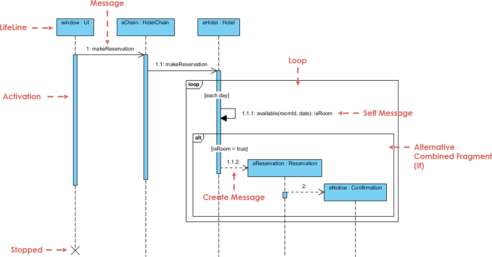
- Lifelines: Vertical dashed lines representing participants (objects, actors, or systems) over time. Time flows from top to bottom.
- Messages: Horizontal arrows indicating communication. Solid arrows typically denote synchronous calls (with expected return), dashed arrows show asynchronous messages or returns.
- Activation Bars (Execution Specifications): Thin rectangles on lifelines showing when a participant is active (processing a request).
- Actors: External entities (e.g., User) initiating interactions, often shown with a stick figure.
- Combined Fragments: Boxes for control structures, such as:
- alt (alternative) for if-else conditions.
- opt for optional flows.
- loop for repetitions.
- Interaction Uses (ref): Reusing common sub-interactions.
- Return Messages: Dashed arrows showing responses or results.
These elements allow modelers to represent complex flows, including success paths and exceptions, in a clear, chronological view.
Case Study: E-Commerce Order Submission Process
Consider a realistic e-commerce scenario where a user places an order via a shopping cart. The process involves validation of address, stock availability, and payment. The system must handle three main paths:

- Success: Valid order → stock reserved → payment processed → order confirmed and delivery scheduled.
- Invalid Address: Early rejection with user prompt.
- Payment Declined: Stock checked but payment fails → error message to user.
This flow includes conditional branching (alt fragments) and error handling, making it a perfect candidate for a sequence diagram.
Participants
- User (Actor)
- Shopping Cart (Interface component)
- Order Service (Core business logic)
- Inventory System (External/back-end check)
- Payment Gateway (External service)
Interpretation of the Diagram
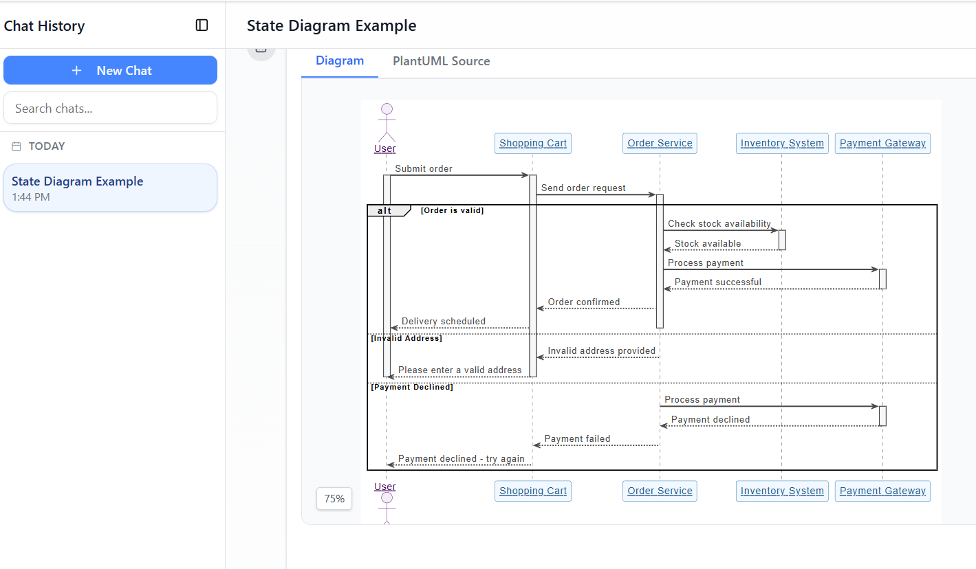
The provided PlantUML-based diagram (generated conceptually from the described flow) shows:
- The process starts with the User submitting an order via the Shopping Cart.
- The Shopping Cart forwards the request to the Order Service.
- An alt fragment branches based on validations:
- [Order is valid] → Order Service checks stock with Inventory System → If available, proceeds to payment → Payment Gateway processes → Success returns confirmation → Order confirmed → Delivery scheduled → User notified.
- [Invalid Address] → Early rejection → Message to user: “Please enter a valid address”.
- [Payment Declined] → Payment attempted but fails → Error: “Payment declined – try again”.
The diagram uses combined fragments (alt) to group conditional paths cleanly. Activation bars show participant processing periods, and dotted return messages indicate responses. This structure keeps the diagram readable while covering happy-path and error scenarios.
Such a diagram helps developers understand message sequencing, identify potential bottlenecks (e.g., external calls to Payment Gateway), and ensure error paths are handled gracefully.
Using Visual Paradigm’s AI Chatbot to Create the Sequence Diagram
Visual Paradigm, a leading UML modeling tool, features an AI Chatbot (accessible via their online platform or desktop app) that revolutionizes diagram creation. Instead of manually dragging lifelines and arrows, users describe the scenario in natural language, and the AI generates a professional, editable UML diagram instantly.
Step-by-Step Process
- Access the AI Chatbot (e.g., at chat.visual-paradigm.com or via Tools > AI Chatbot in Visual Paradigm).
- Select or specify “UML Sequence Diagram” as the type.
- Provide a clear textual description, such as the one in this case study: “A user submits an order from the shopping cart. The order service validates the address and stock. If invalid address, prompt user. If valid, check inventory. If stock available, process payment via gateway. If payment succeeds, confirm order and schedule delivery. Include branches for invalid address and payment declined.”
- Refine via conversation: Ask the AI to add details (e.g., “Add activation bars” or “Include return messages for failures”).
- Generate: The AI produces the diagram (often in editable format, with PlantUML source if needed).
- Edit & Export: Refine manually (adjust layout, labels), then export as image, PDF, or code.
In this case study, the diagram closely matches what the AI would output from the provided description — complete with alt fragments for branches, proper message directions, and clean lifelines. The tool ensures UML compliance, balanced layout, and readability.
Benefits observed:
- Speed: From text to diagram in seconds.
- Accuracy: AI applies correct notation for fragments and messages.
- Iteration: Chat-based refinement allows quick adjustments without redrawing.
How to Use Sequence Diagrams Effectively
Sequence diagrams shine in:
- Requirements analysis → Clarify use case flows with stakeholders.
- Design phase → Detail interactions before coding.
- Documentation → Explain system behavior to teams or for onboarding.
- Debugging → Compare expected vs. actual message sequences.
- Testing → Derive test cases from success/error paths.
Best practices:
- Keep diagrams focused on one use case or scenario.
- Use meaningful names for messages (e.g., “checkStock()” instead of vague terms).
- Limit participants to 5–7 for readability.
- Combine with other UML diagrams (e.g., use case diagrams for context, class diagrams for structure).
Conclusion
This e-commerce order process case study demonstrates how sequence diagrams effectively model real-world interactions with conditional logic and error handling. By leveraging Visual Paradigm’s AI Chatbot, creating such diagrams becomes accessible and efficient — shifting focus from manual drawing to high-level thinking and refinement.
Modern tools like this lower the barrier for developers, analysts, and architects, enabling faster iteration and better communication in software projects. Whether you’re designing a simple checkout or a complex distributed system, sequence diagrams — powered by AI — remain an essential tool for understanding and building reliable systems.
Articles and resources
- AI Sequence Diagram Example: Video Streaming Playback Initiation: This example shows the AI Chatbot acting as a modeling partner to interpret intent and refine the logic for starting video playback in real time.
- Enroll in Course Example | AI MVC System Architecture Generator: This resource demonstrates how an e-learning use case is expanded into MVC architecture to generate MVC sequence diagrams automatically.
- PlantUML Sequence Diagram Builder: A tool that provides a visual PlantUML generator to define participants and messages for professional UML sequence diagrams.
- Visual Paradigm – AI-Powered UML Sequence Diagrams: An article explaining how to generate sequence diagrams instantly using artificial intelligence within the modeling suite.
- AI-Powered Sequence Diagram Refinement Tool: This feature explores how AI improves UML modeling by optimizing sequence diagrams with intelligent suggestions.
- Comprehensive Tutorial: Using the AI Sequence Diagram Refinement Tool: A step-by-step guide on leveraging AI to enhance the accuracy, clarity, and consistency of sequence models.
- Simplify Complex Workflows with AI Sequence Diagram Tool: An exploration of how the AI-enhanced tool simplifies the modeling of complex system interactions.
- Beginner’s Tutorial: Create Professional Sequence Diagrams in Minutes: A hands-on guide for beginners to generate their first professional diagram using natural language prompts and the AI chatbot.
- Mastering Sequence Diagrams with AI Chatbot: E-commerce Case Study: This tutorial uses a real-world e-commerce scenario to demonstrate conversational diagramming with the AI chatbot.
- AI-Powered Sequence Diagram Refinement from Use Case Descriptions: This resource details how to transform use-case descriptions into precise sequence diagrams with minimal manual effort via the AI refinement tool.