


Enterprise architecture relies heavily on clear communication. Without a standard language, stakeholders struggle to understand complex system interactions. ArchiMate serves as this standard language. It provides a framework for modeling enterprise architecture. This guide focuses on the notation itself. We will explore the visual elements, relationships, and structure required to build effective models.
Notation is the foundation of any architectural diagram. It ensures that everyone interprets the model in the same way. This tutorial covers the core components. It avoids specific software tools. Instead, it focuses on the principles of the notation. By the end, you will be able to read and create diagrams that adhere to the standard.
Why Notation Matters in Enterprise Architecture 📐
Complex systems involve many moving parts. Different teams manage different layers. A developer speaks a different language than a business manager. ArchiMate bridges this gap. It creates a unified view of the organization.
- Clarity: Visual representations reduce ambiguity.
- Consistency: Standard symbols ensure uniform interpretation.
- Communication: Stakeholders can discuss architecture without confusion.
- Analysis: Models allow for impact analysis and gap analysis.
Without a standardized notation, diagrams become personal art. They lose their utility as technical documentation. ArchiMate notation prevents this. It defines strict rules for shapes and lines. Following these rules is essential for professional modeling.
The Core Layers of ArchiMate 🌐
The architecture is divided into distinct layers. This separation helps manage complexity. Each layer represents a specific domain of the enterprise. Understanding these layers is the first step in creating a diagram.
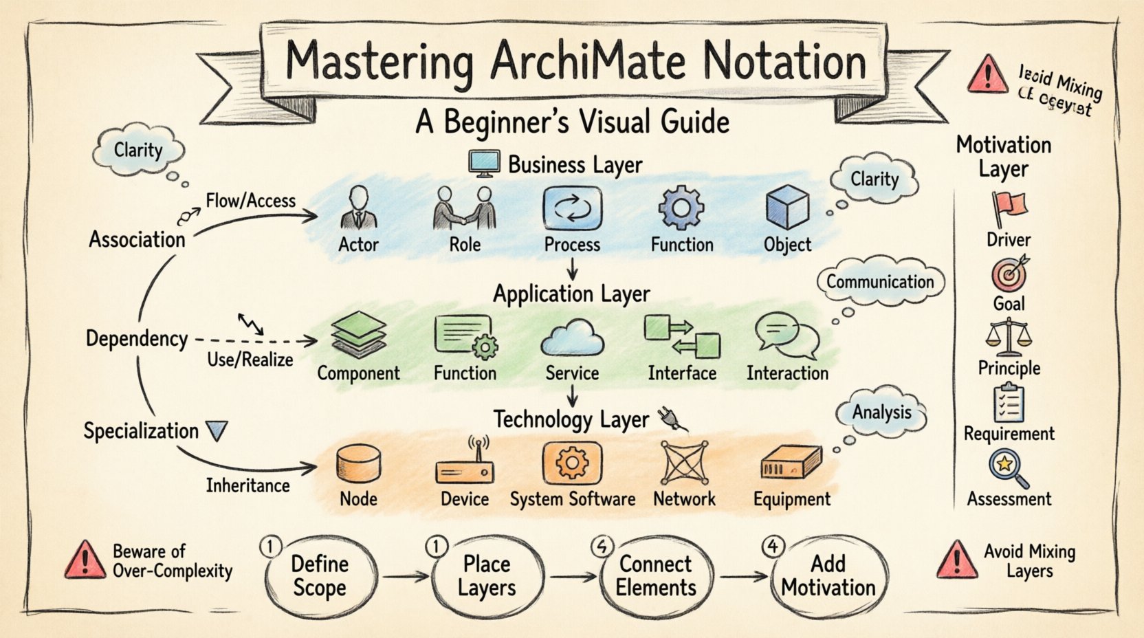
1. Business Layer 🏢
This layer represents the business structure. It includes processes, roles, and organizational units. It focuses on the value chain. It describes how the organization operates.
- Business Actor: A person or organization performing a role.
- Business Role: A collection of responsibilities assigned to an actor.
- Business Process: A set of activities that achieve a specific goal.
- Business Function: A set of responsibilities and activities.
- Business Object: A thing that is relevant to the business.
2. Application Layer 💻
This layer describes the software systems. It covers applications and their interactions. It focuses on the technical implementation of business functions.
- Application Component: A modular part of a software system.
- Application Function: A function performed by an application.
- Application Service: A set of functions exposed to the outside.
- Application Interface: A boundary between two components.
- Application Interaction: A communication between components.
3. Technology Layer 🔌
This layer represents the physical infrastructure. It includes hardware and system software. It supports the application layer.
- Node: A computational resource.
- Device: A physical device with computational capacity.
- System Software: Software that manages hardware resources.
- Network: A communication infrastructure.
- Equipment: Physical hardware components.
These three layers form the structural foundation. They allow you to map business needs to technical solutions. You can see how a business process triggers an application function. That function might run on a specific node in the technology layer.
The Motivation Layer 🎯
Structural elements alone do not tell the whole story. You need to understand the why behind the architecture. The motivation layer captures this intent. It defines the drivers, goals, and principles.
- Driver: A factor that influences a goal or outcome.
- Goal: A desired outcome to be achieved.
- Principle: A rule that guides decision-making.
- Requirement: A constraint or need for the system.
- Assessment: A judgment of compliance or success.
Linking motivation to structure is powerful. You can show which goal drives a specific business process. You can demonstrate which principle dictates a technology choice. This adds context to the static diagrams.
Relationships and Connections 🔗
Elements are rarely isolated. They interact with one another. ArchiMate defines specific relationship types. These lines describe how elements influence each other. There are three main types of relationships.
1. Association Relationships 🔗
Association indicates a usage or communication link. It is the most common relationship. It shows how one element interacts with another.
- Flow: Indicates the flow of information or material.
- Access: Indicates the use of data or objects.
2. Dependency Relationships 📉
Dependency shows that one element relies on another. If the supplier changes, the client is affected.
- Dependency: General reliance between elements.
- Realization: One element implements or realizes another.
3. Specialization Relationships 🔻
Specialization indicates an inheritance or type hierarchy. It shows that one element is a specific version of another.
- Specialization: A more specific element derived from a general one.
- Aggregation: A whole-part relationship where parts can exist independently.
Relationship Types Table
| Relationship Type | Description | Example |
|---|---|---|
| Association | Interaction or flow | Process uses Application Service |
| Dependency | Reliance or implementation | Application realizes Business Process |
| Specialization | Inheritance or type hierarchy | Specific Role is a type of General Role |
| Assignment | Linking actor to role | Employee performs Role |
| Aggregation | Whole-part relationship | Business Process consists of Activities |
Structuring Your Model 📝
Creating a diagram involves organizing elements logically. There are specific guidelines for layout. This ensures the diagram is readable. Avoid crossing lines where possible. Use alignment to group related items.
Step 1: Define the Scope
Start with a clear boundary. What is included in the view? What is excluded? A focused diagram is more effective than a sprawling one. Define the layer focus. Is this a business view or a technical view?
Step 2: Place the Layers
Arrange layers vertically. Business at the top. Application in the middle. Technology at the bottom. This reflects the hierarchy of dependency. Business needs drive application functions, which run on technology.
Step 3: Connect the Elements
Draw relationships based on the standard types. Use distinct line styles for different relationship types. Solid lines for association. Dashed lines for dependency. Curved lines for specialization. This visual distinction aids comprehension.
Step 4: Add Motivation
Include the business drivers. Place them in a separate motivation area. Connect them to the structural elements they influence. This provides the context for the design decisions.
Best Practices for Notation 🛠️
Adhering to conventions improves quality. Here are recommendations for creating robust models.
- Consistency is Key: Use the same symbols for the same concepts throughout the model.
- Limit Diagram Complexity: One diagram, one story. Do not cram every element into one view.
- Use White Space: Allow elements to breathe. Cluttered diagrams are hard to read.
- Label Clearly: Every element needs a clear name. Avoid abbreviations unless defined.
- Check Layer Boundaries: Ensure elements do not cross layer boundaries inappropriately. Exceptions exist but should be intentional.
- Validate Relationships: Ensure relationships are semantically correct. A technology node cannot directly perform a business process without an application layer.
Common Pitfalls to Avoid ⚠️
Beginners often make specific mistakes. Being aware of them helps you avoid them.
- Mixing Layers Indiscriminately: Connecting a Business Actor directly to a Technology Node without an Application layer is usually incorrect. It skips the logic of how software executes the business logic.
- Overusing Relationships: Connecting every element to every other element creates a “spaghetti diagram”. Use relationships only where there is a meaningful interaction.
- Ignoring the Motivation Layer: Focusing only on structure ignores the drivers. This leads to architecture that does not support business goals.
- Inconsistent Naming: Calling the same concept “App” in one diagram and “System” in another confuses readers. Use standard terminology.
- Ignoring the Data Layer: While often integrated with the Application layer, data objects are crucial. Ensure data flow is represented where relevant.
Advanced Notation Concepts 🚀
Once the basics are understood, you can explore more advanced features. These add depth to your models.
Implementation and Migration
Architecture is not static. It evolves. The Implementation and Migration layer helps plan the transition. It describes how to move from the current state to a target state.
- Work Package: A set of activities to achieve a goal.
- Project: A temporary endeavor undertaken to create a unique result.
- Gap: A difference between the current and target state.
Event Triggers
Some elements are triggered by events. An event is an occurrence that influences the behavior of a process. You can model this by linking an event to a business process or application function.
Creating Your First Model 🎨
Now, put the knowledge into practice. Follow this workflow to build a simple diagram.
- Identify the Goal: What are you modeling? (e.g., A new reporting process).
- Select the Layer: Decide which layer is the focus. Start with the Business Layer.
- Define Actors and Roles: Who is involved? (e.g., Analyst, Manager).
- Define Processes: What steps are taken? (e.g., Collect Data, Analyze Data).
- Define Objects: What data is used? (e.g., Report, Customer Record).
- Connect Elements: Draw the flows and assignments.
- Review: Check for consistency and clarity.
This process can be repeated for other layers. Ensure the connections between layers are logical. For instance, a Business Process should be supported by an Application Function.
Conclusion 📚
ArchiMate notation provides a robust framework for enterprise architecture. It enables clear communication across different domains. By understanding the layers, elements, and relationships, you can create effective models. Focus on consistency and clarity. Avoid clutter. Always link structure to motivation. With practice, you will be able to model complex systems with confidence.
Remember, the goal is not just to draw. The goal is to understand. Use the notation as a tool for thinking. It helps identify gaps, redundancies, and opportunities for improvement. Start small. Build your understanding layer by layer. The notation is a language. Learn it well, and it will serve your organization effectively.