
Introduction
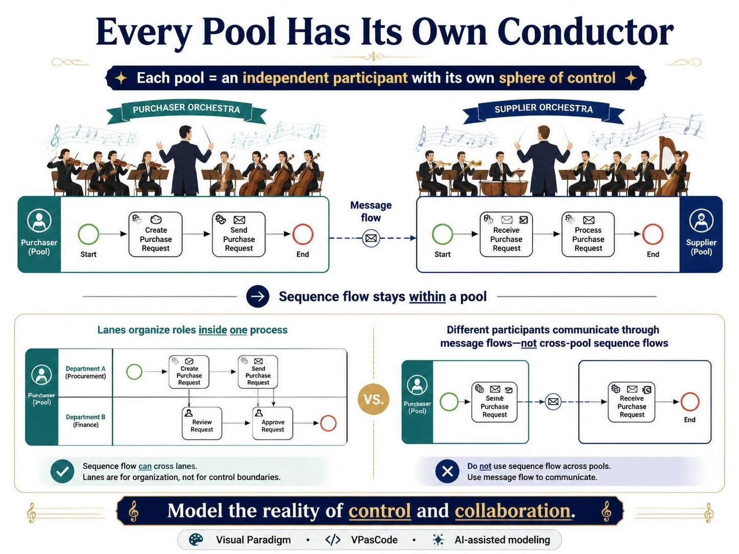
In Business Process Model and Notation (BPMN), the pool is one of the most misunderstood yet powerful constructs available to process modelers. Unlike lanes, which simply partition tasks within a single process, pools represent independent process participants—each with its own conductor, its own orchestra, and its own sphere of control. Understanding pools is essential for anyone who wants to model collaboration between organizations, departments, or systems accurately.
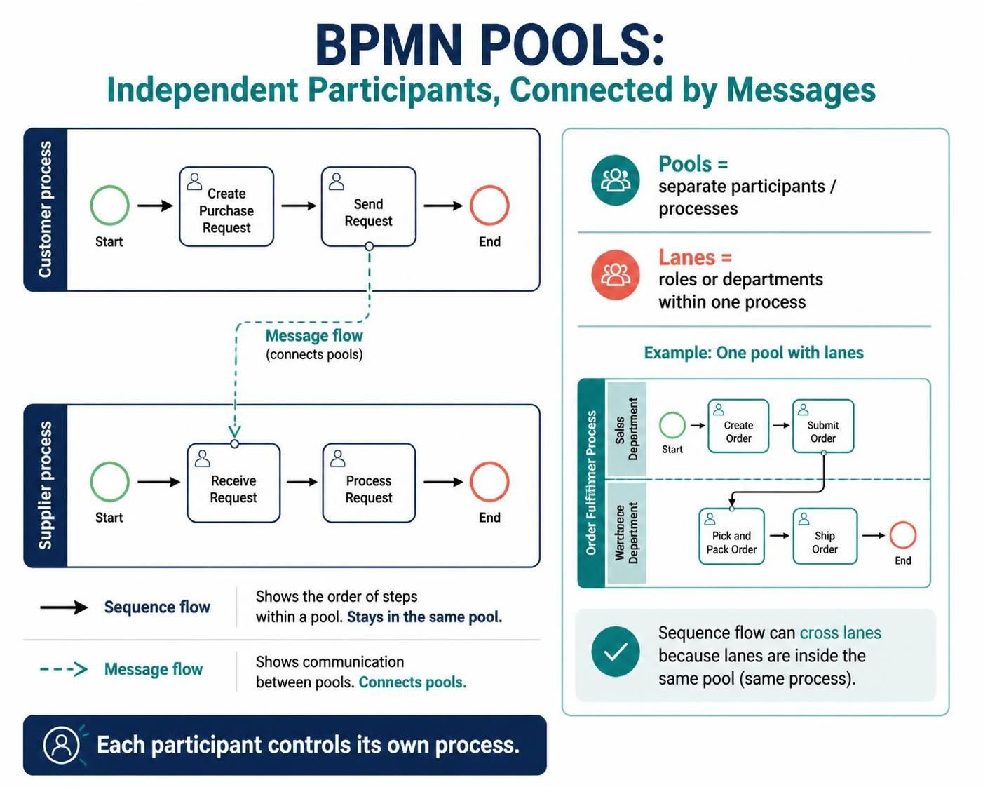
This guide explores the central idea behind pools: that each pool represents a self-contained process with its own control flow, and that collaboration between pools is expressed through message flows rather than sequence flows. We will examine how this differs from the lane-based orchestration model, why it matters for aligning business and IT, and how to model collaboration effectively using PlantUML and modern tooling such as Visual Paradigm.
Key Concepts
1. Pool as Process Conductor (Orchestration)
A pool always contains lanes, and the lane boundaries represent process boundaries from start to end. To BPMN, the pool represents a higher-ranking instance compared to its lanes. The pool assumes process control—in other words, it assigns the tasks. It behaves like the conductor of an orchestra, and so this type of process is called orchestration.
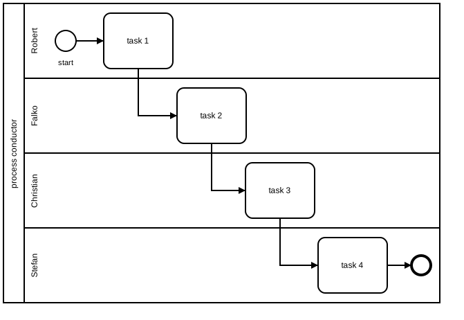
In the diagram above, the “conductor” arranges for Falko to process task 2 as soon as Robert completes task 1. The conductor has the highest-level control of the process, and each instrument in the orchestra plays the tune the conductor decides upon.
2. The Coordination Alternative
Many experienced process modelers struggle with this way of thinking. They prefer to model a process sequence where no almighty conductor exists in their company, and individual process participants coordinate and cooperate on their own.
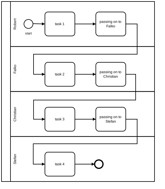
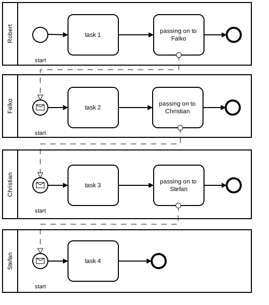
To coordinate cooperation with BPMN requires explicit modeling. You assign each task manager a separate pool, and the process passes from one to the next as a message flow. In principle, this creates four independent conductors—each with control over their respective mini-processes, but able only to send messages that trigger their successor processes.
3. The Process Engine as Conductor
Even though BPMN lanes look very much like those of other process notations, they represent an entirely different way of thinking, attributable to BPMN’s origin in the world of process automation. In that world, the process engine controls all tasks in the process, even though different task managers may execute them. The process engine equates to the mysterious, almighty process conductor.
This is closely related to service orchestration in Service Oriented Architecture (SOA)—except that these services are not only fully automated web services; they can also be tasks executed by human process participants as directed by the process engine.
4. Pools and Collaboration Diagrams
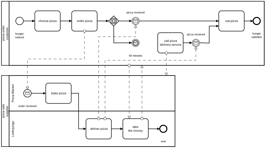
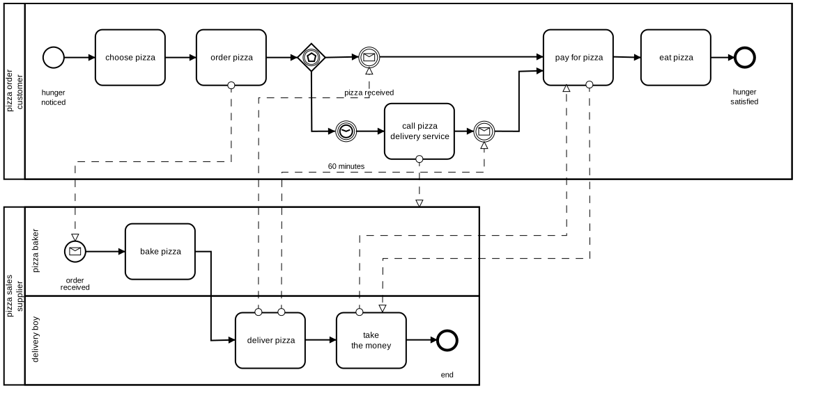
When two independent processes interact—such as a customer ordering a pizza and a delivery service fulfilling it—BPMN models this as a collaboration diagram with two pools connected by message flows.
5. Collapsed Pools (Black-Box Pools)
It often happens that we don’t know the processes of all parties in detail. As long as partners adhere to agreed-upon interfaces—receiving or sending certain messages—things can still operate smoothly. In such cases, we can collapse the pool to hide internal details.
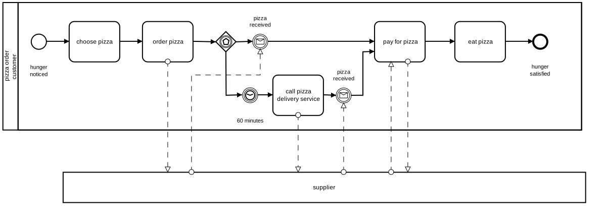
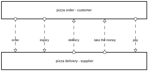
We could go a step further and collapse the customer’s pool too. Now we see only the messages exchanged—though we lose visibility into interdependencies and conditions.
6. Lanes vs. Pools: A Pragmatic Choice
You can eliminate pools and work just with lanes, modeling the message exchange as normal tasks. That’s traditional and pragmatic during a transitional period. In the medium and long terms, however, avoiding pools denies you a powerful device for increasing the significance of process models—especially when striving to harmonize functional and technical process models for better business-IT alignment.
Tooling: Visual Paradigm BPMN + VPasCode + AI-Assisted Features
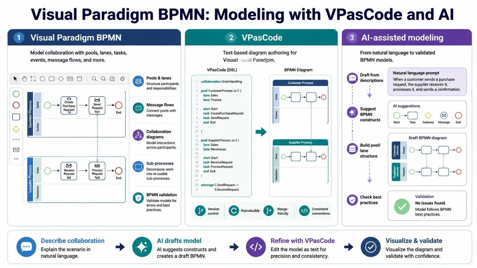
While PlantUML offers a lightweight, text-based approach to BPMN modeling, Visual Paradigm provides a full-featured, BPMN 2.0-compliant environment—especially valuable when pools, message flows, and collaboration diagrams are central to your model.
Visual Paradigm BPMN
Visual Paradigm supports the complete BPMN 2.0 specification, including:
-
Pools and Lanes with drag-and-drop creation
-
Message Flows between pools (including collapsed/black-box pools)
-
Collaboration Diagrams with multiple participants
-
Expanded and Collapsed Sub-Processes
-
Validation against BPMN rules
VPasCode: Diagram-as-Code for Visual Paradigm
VPasCode brings the “diagrams-as-code” philosophy to Visual Paradigm. Instead of manually dragging shapes, you can define BPMN models in a textual DSL and generate the corresponding diagrams. This is ideal for:
-
Version control – textual BPMN definitions live comfortably in Git
-
Reproducibility – regenerate diagrams deterministically
-
Collaboration – multiple modelers can merge changes cleanly
-
Consistency – enforce naming and structural conventions
AI-Assisted Modeling
Visual Paradigm’s AI-assisted features can accelerate BPMN modeling by:
-
Generating initial process sketches from natural-language descriptions
-
Suggesting appropriate BPMN constructs (e.g., when to use a message flow vs. a sequence flow)
-
Auto-completing pool/lane structures based on participant roles
-
Validating models against best practices and BPMN 2.0 rules
Combining VPasCode’s textual precision with AI-assisted generation gives teams a powerful workflow: describe the collaboration in natural language, let AI draft the model, refine it in code, and visualize it in Visual Paradigm—all while maintaining full BPMN 2.0 compliance.
Conclusion
Pools are more than a visual grouping mechanism—they embody a fundamental principle of BPMN: that each process participant is an independent conductor with its own sphere of control. Collaboration between participants is modeled explicitly through message flows, not implicitly through sequence flows across lane boundaries. This distinction, rooted in BPMN’s origins in process automation and service orchestration, becomes increasingly important as organizations seek to align business and IT.
Whether you choose the pragmatic lane-only approach during a transitional period, or embrace full collaboration diagrams with multiple pools, understanding the conductor-and-orchestra metaphor will make your models more meaningful and more faithful to reality. With tools like Visual Paradigm, VPasCode, and AI-assisted modeling, implementing this principle has never been more accessible.
Reference
-
BPMN Text to Diagram with VPasCode: A User-Friendly BPMN PlantUML Tool: Official release detailing how to draft BPMN diagrams using human-readable PlantUML-style text syntax with AI generation support .
-
VPasCode: AI-Assisted Diagram-as-Code with PlantUML, Mermaid, and Graphviz: Comprehensive guide covering version control, CI/CD workflows, and prompt engineering for AI-assisted diagram creation .
-
BPMN Business Process Diagram in Visual Paradigm: Step-by-step tutorial on creating BPMN 2.0 compliant diagrams using the desktop visual editor with swimlanes and validation .
-
Why AI-Assisted + Diagram As Code is the Perfect Match for BPMN in Modern Agile Teams: Blog post discussing how AI and diagram-as-code principles address the friction of manual BPMN drafting in agile environments .
-
AI BPMN Diagram Generator: Professional BPD Tool: Guide on using the AI generation feature within Visual Paradigm Desktop to create BPMN diagrams from plain language descriptions with pools and lanes .
-
VPasCode Deep Dive: Unifying Mermaid, PlantUML, and AI in One Platform: Article explaining how VPasCode consolidates multiple text-to-diagram engines alongside AI capabilities to reduce tool fragmentation .
-
How to Create BPMN Business Process Diagrams with Visual Paradigm Desktop: Practical walkthrough for building process flows with the Resource Catalog, gateways, and process simulation features .