


In modern software development, use case-driven design is a cornerstone of effective system modeling. It focuses on capturing user goals and system behaviors through real-world scenarios. At the heart of this approach lies the UML sequence diagram—a powerful visual tool that brings use cases to life by showing how objects interact over time.
This comprehensive guide is designed for beginners and teams who want to understand:
-
What sequence diagrams are and why they matter
-
How to create them using a use case-driven approach
-
Key concepts and real-world examples
-
How Visual Paradigm’s AI Sequence Diagram Generator accelerates the entire process—making modeling faster, smarter, and more collaborative.
🎯 What Is a Use Case-Driven Approach?
A use case-driven approach centers system design around user goals. Each use case describes a specific interaction between a user (actor) and the system to achieve a meaningful outcome.
Example:
“As a customer, I want to log in to my account so I can view my order history.”
Use cases are not just documentation—they are blueprints for functionality, and sequence diagrams are the ideal way to visualize how those use cases unfold in real time.
🧩 Why Use Sequence Diagrams in Use Case-Driven Development?
Sequence diagrams are uniquely suited to support use case modeling because they:
✅ Show the dynamic flow of interactions
✅ Highlight timing and order of messages
✅ Clarify responsibilities between objects
✅ Expose edge cases (e.g., invalid input, timeouts)
✅ Support validation of use cases during design and testing
✅ Improve communication between developers, testers, and stakeholders
🔍 Without sequence diagrams, use cases can remain abstract. With them, they become executable blueprints.
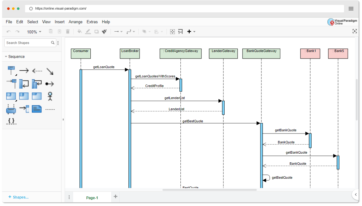
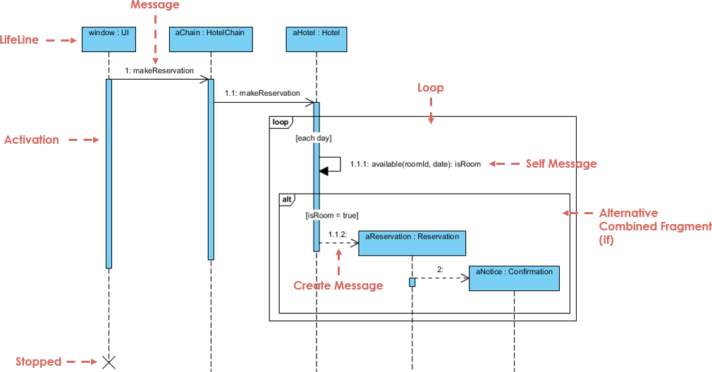
📌 Key Concepts of UML Sequence Diagrams (Beginner-Friendly)
Before diving into use cases, let’s master the core building blocks:
| Element | Description | Visual |
|---|---|---|
| Lifelines | Vertical dashed lines representing objects or actors. Shows existence over time. | ─────────────── |
| Messages | Horizontal arrows between lifelines. Show communication. | |
| • Synchronous | Solid arrow with filled head. Caller waits for response. | ➔ |
| • Asynchronous | Solid arrow with open head. No wait. | ➝ |
| • Return | Dashed arrow (response). | ➝ |
| • Self-message | Arrow looping back to same lifeline (internal processing). | ↺ |
| Activation Bars | Thin rectangles on lifelines showing when an object is active. | ▯▯▯ |
| Combined Fragments | Boxes that represent control logic: | |
• alt |
Alternatives (if/else) | alt: success / failure |
• opt |
Optional (may or may not happen) | opt: print receipt |
• loop |
Repetition (e.g., while loop) | loop: retry 3 times |
• par |
Parallel execution | par: check payment & stock |
| Creation/Deletion | create message or “X” at the end of a lifeline |
create: User or X |
💡 Tip: Always start with a use case, then map it to a sequence diagram.
🔄 How to Create a Sequence Diagram from a Use Case (Step-by-Step)
Let’s walk through a real-world example using a use case-driven approach.
📌 Example: Use Case – “User Logs In to System”
Use Case Text:
As a user, I want to log in to my account using my username and password so I can access my profile.
Step 1: Identify Actors and Objects
-
Actor:
User -
Objects:
LoginView,LoginController,Database
Step 2: Define the Main Flow
-
User→LoginView: Enters username/password -
LoginView→LoginController: Sends credentials -
LoginController→Database: Checks if user exists -
Database→LoginController: Returns result -
LoginController→LoginView: Sends success/failure -
LoginView→User: Displays message
Step 3: Add Control Logic with Combined Fragments
Use an alt fragment to show:
-
Success path: “Login successful”
-
Failure path: “Invalid credentials”
✅ This captures the decision point in the use case.
Step 4: Add Activation Bars
-
Add activation bars to
LoginControllerandDatabaseto show processing time.
Step 5: Final Diagram
Now you have a complete, use case-aligned sequence diagram that reflects real system behavior.
🔗 See this in action: AI-Powered UML Sequence Diagrams
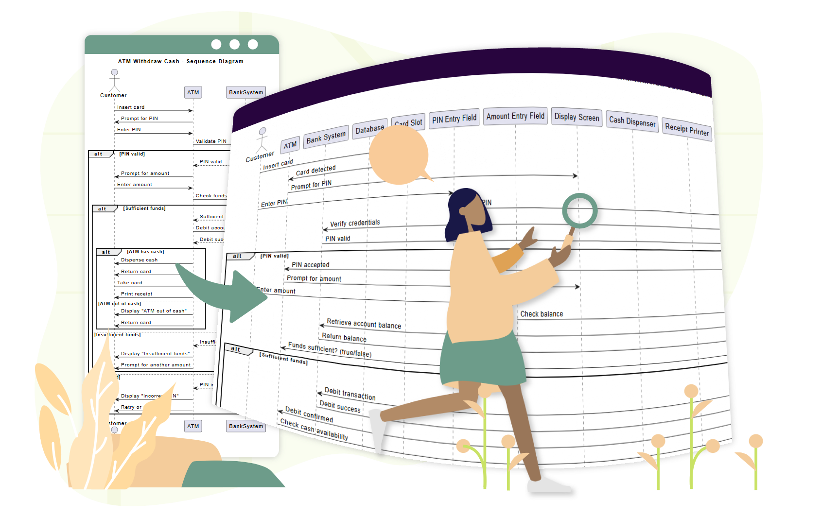
📌 Example 2: Use Case – “Customer Withdraws Cash from ATM”
Use Case Text:
As a customer, I want to withdraw cash from an ATM so I can access my money. If the balance is insufficient, I want to be notified.
Step 1: Identify Participants
-
Actor:
Customer -
Objects:
ATM,CardReader,BankServer,CashDispenser
Step 2: Main Flow
-
Customer→ATM: Inserts card -
ATM→CardReader: Reads card -
ATM→Customer: Prompts for PIN -
Customer→ATM: Enters PIN -
ATM→BankServer: Validates PIN -
BankServer→ATM: Confirms valid -
ATM→Customer: Prompts for amount -
Customer→ATM: Enters amount -
ATM→BankServer: Checks balance -
BankServer→ATM: Returns balance -
ATM→CashDispenser: Dispenses cash -
ATM→Customer: Shows receipt option
Step 3: Add Fragments
-
loop: For retry attempts after wrong PIN -
opt: For receipt printing -
alt: For “insufficient funds” vs. “success”
🔗 See how AI handles this: Simplify Complex Workflows with AI Sequence Diagram Tool
📌 Example 3: Use Case – “Customer Completes E-Commerce Checkout”
Use Case Text:
As a customer, I want to add items to my cart, proceed to checkout, and complete payment so I can receive my order.
Step 1: Participants
-
Customer,ShoppingCart,PaymentGateway,InventorySystem,OrderConfirmation
Step 2: Flow with Parallelism
-
Customer→ShoppingCart: Adds item(s) →loopfor multiple items -
ShoppingCart→Customer: Shows total -
Customer→PaymentGateway: Initiates payment -
Customer→InventorySystem: Requests stock check -
PaymentGateway→Bank: Processes payment →parwith inventory check -
InventorySystem→PaymentGateway: Confirms availability -
PaymentGateway→ShoppingCart: Confirms order -
ShoppingCart→OrderConfirmation: Sends confirmation
✅ Use
parfragment to show concurrent processing.
🔗 See a full tutorial: Mastering Sequence Diagrams with AI Chatbot: E-commerce Case Study
🤖 How Visual Paradigm’s AI Sequence Diagram Generator Helps Teams
Traditional modeling tools require users to manually drag lifelines, draw messages, and place fragments—time-consuming and error-prone.

Visual Paradigm’s AI-powered tools eliminate these bottlenecks, especially for teams using a use case-driven approach.
✨ 1. AI Chatbot: Generate Diagrams from Use Case Text in Seconds
Instead of drawing by hand, describe your use case in plain English:
📝 Prompt:
“Generate a sequence diagram for a user logging in with username/password, including error handling and retry after 3 failed attempts.”
The AI:
-
Identifies actors and objects
-
Maps the use case flow to lifelines and messages
-
Applies
alt,loop, andoptfragments automatically -
Outputs a clean, professional diagram in under 10 seconds
🔗 Try it: AI-Powered UML Sequence Diagrams
✨ 2. AI Sequence Diagram Refinement Tool: Turn Drafts into Professional Models
Even if you start with a rough sketch, the AI Sequence Diagram Refinement Tool enhances it:
-
Adds activation bars where needed
-
Suggests correct fragment usage (
alt,loop,par) -
Enforces design patterns (e.g., MVC: View → Controller → Model)
-
Detects missing error paths and edge cases
-
Improves readability and consistency
🔗 Learn how: Comprehensive Tutorial: Using the AI Sequence Diagram Refinement Tool
✨ 3. From Use Case Descriptions to Diagrams: Zero Manual Translation
No more translating use case text into diagrams by hand.
The AI automatically converts textual use cases into accurate sequence diagrams, reducing:
-
Manual effort
-
Misinterpretation
-
Inconsistencies
🔗 See it in action: AI-Powered Sequence Diagram Refinement from Use Case Descriptions
✨ 4. Iterative Refinement with Conversational AI
Want to improve your diagram? Just chat with the AI:
-
“Add a ‘Forgot Password’ option after 3 failed login attempts.”
-
“Change ‘User’ to ‘Customer’.”
-
“Show the error message in red.”
Each prompt updates the diagram in real time—no redrawing, no frustration.
🔗 Explore the interface: AI Sequence Diagram Refinement Tool Interface
✨ 5. Team Collaboration Made Easy
-
Non-technical stakeholders (product managers, clients) can contribute via natural language.
-
Developers can refine diagrams quickly during sprints.
-
Testers can use diagrams to write test cases.
-
Designers can validate flows before coding.
✅ Ideal for agile teams using user stories and use cases.
🚀 Why Teams Love Visual Paradigm’s AI for Use Case Modeling
| Benefit | Impact |
|---|---|
| ⏱️ Speed | Generate diagrams in seconds instead of hours |
| 🧠 Low Skill Barrier | No UML expertise needed to start |
| 🔄 Iterative Design | Refine diagrams in real time via chat |
| 🛠️ Error Reduction | AI catches missing flows, invalid fragments |
| 📦 Export & Share | Export to PNG, SVG, PDF, or embed in Confluence/Notion |
| 🤝 Collaboration | Everyone can contribute, even non-technical members |
📚 Top Resources for Beginners & Teams
✅ Final Tips for Teams Using Use Case-Driven Design
-
Start with a clear use case – define the user goal first.
-
Use sequence diagrams to validate the flow before coding.
-
Involve stakeholders early – use diagrams for feedback.
-
Leverage AI to reduce manual work – let the tool do the heavy lifting.
-
Keep diagrams updated – revise as requirements evolve.
🎁 Get Started for Free
You don’t need a paid license to experience the power of AI-driven modeling.
-
Try the free Community Edition of Visual Paradigm – includes AI Chatbot and sequence diagram tools.
-
Use the AI Sequence Diagram Refinement Tool online.
-
Join a growing community of teams using AI to build better systems faster.
📌 Conclusion
A use case-driven approach is the foundation of user-centered software design. UML sequence diagrams bring those use cases to life—showing who does what, when, and how.
With Visual Paradigm’s AI Sequence Diagram Generator, teams can:
-
Generate diagrams from plain language
-
Refine them in real time
-
Ensure consistency and accuracy
-
Collaborate across roles
🚀 From use case to diagram in seconds—no UML expertise needed.
👉 Start today with the free Community Edition and transform your team’s modeling workflow.
🌟 The future of system design is not just visual—it’s intelligent.
Let AI be your modeling partner.