Creating a robust data structure is the foundation of any reliable software application. When you start building systems that store information, you need a blueprint. That blueprint is the Entity Relationship Diagram, commonly known as an ERD. This visual representation allows developers and stakeholders to understand how data connects before a single line of code is written. Without this planning phase, databases often become cluttered, slow, and difficult to maintain. 🏗️
This guide breaks down the core principles of ERD design. We will explore the essential components, the rules governing data relationships, and the logical steps required to build a schema that scales. Whether you are a student, a junior developer, or a product manager, understanding these concepts ensures your data architecture remains sound over time.
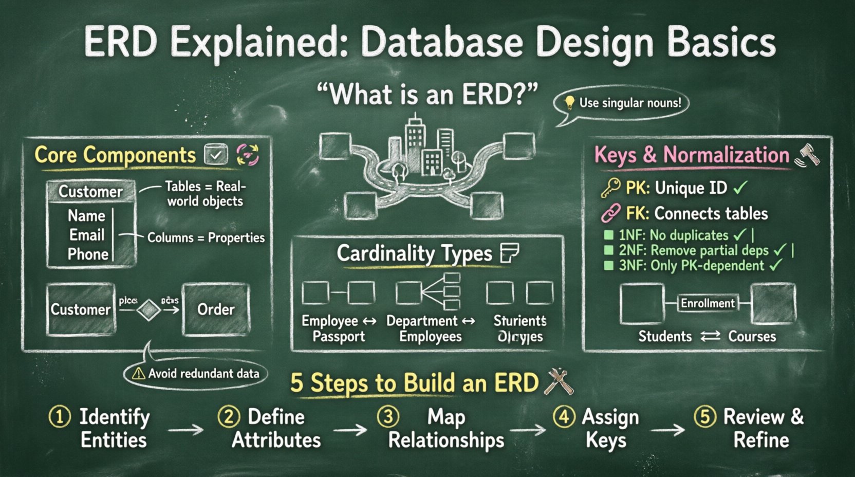
What Exactly Is an ERD? 🤔
An Entity Relationship Diagram is a high-level model used to describe the structure of a database. It maps out the entities, which represent real-world objects or concepts, and the relationships that exist between them. Think of it as a map for your data. Just as a city map shows roads connecting neighborhoods, an ERD shows tables connecting specific data points.
The primary goal of this diagram is to communicate the logical structure of the database. It serves as a universal language between technical teams and business analysts. By visualizing the data flow, you can identify potential issues early, such as redundant data or missing links. This proactive approach saves significant time during the development phase.
Key benefits of using an ERD include:
- Clarity: Visualizing complex data structures makes them easier to understand.
- Consistency: Ensures all team members agree on how data is defined.
- Efficiency: Helps optimize query performance by reducing unnecessary joins.
- Documentation: Acts as a reference guide for future maintenance.
The Core Components of a Database Schema 🔑
To build a diagram effectively, you must understand the building blocks. Every diagram relies on three main elements: entities, attributes, and relationships. Mastering these basics provides the necessary framework for any database project.
1. Entities: The Tables 📦
An entity represents a specific object, person, or concept within the business domain. In a relational database, an entity corresponds to a table. Each table stores unique information about that entity. For example, in a library system, “Book” and “Member” are distinct entities.
Entities are typically represented as rectangles in the diagram. They should be named using singular nouns to indicate individual instances. When defining an entity, you are essentially defining a category of data.
- Strong Entities: These exist independently. A “Customer” table exists even without other tables.
- Weak Entities: These depend on another entity for their existence. An “Order Item” might be a weak entity because it relies on an “Order” to make sense.
2. Attributes: The Columns 📝
Attributes are the properties or characteristics that describe an entity. In a database table, these become the columns. For instance, a “Customer” entity might have attributes like Name, Email, and Phone Number.
Attributes can be classified into several types:
- Simple Attributes: Cannot be divided further, such as Age or Date of Birth.
- Composite Attributes: Can be divided into sub-parts, such as Address (Street, City, Zip).
- Multi-valued Attributes: Can hold multiple values, such as Skills or Phone Numbers.
- Derived Attributes: Calculated from other attributes, such as Age (derived from Date of Birth).
3. Relationships: The Connections 🔄
Relationships define how entities interact with one another. This is the most critical part of the design because it dictates how data is linked. In the diagram, relationships are shown as diamonds or lines connecting the entities.
For example, a “Customer” places an “Order”. This is a relationship. The database must enforce rules to ensure a customer exists before an order can be assigned to them. This prevents orphaned data.
Understanding Cardinality and Modality 📏
Cardinality defines the numerical relationship between records in two related tables. It answers the question: “How many instances of Entity A relate to how many instances of Entity B?”. Understanding this prevents data anomalies.
There are three primary types of cardinality:
- One-to-One (1:1): One record in Table A relates to exactly one record in Table B.
- One-to-Many (1:N): One record in Table A relates to many records in Table B.
- Many-to-Many (M:N): Many records in Table A relate to many records in Table B.
Below is a table illustrating these relationships with practical examples.
| Cardinality Type | Example Scenario | Implementation |
|---|---|---|
| One-to-One (1:1) | Employee to Passport | Foreign key in one table |
| One-to-Many (1:N) | Department to Employees | Foreign key in the “Many” table |
| Many-to-Many (M:N) | Students to Courses | Intermediate Junction Table |
Modality adds another layer of detail. It specifies whether a relationship is mandatory or optional. For instance, can an Order exist without a Customer? Usually, no. This is a mandatory relationship. Can a Customer have no Orders? Yes, this is optional.
Keys: The Glue of Data Integrity 🔗
Keys are specific attributes used to identify records uniquely or link tables together. They are the mechanism that enforces relationships and maintains data integrity.
Primary Keys
A Primary Key (PK) uniquely identifies each record in a table. No two rows can have the same primary key value. It cannot be null. Common choices include auto-incrementing integers or UUIDs. This ensures every piece of data has a unique address.
Foreign Keys
A Foreign Key (FK) is a field in one table that refers to the Primary Key in another table. It establishes the link between the two. When you define a foreign key, the database management system enforces referential integrity. This means you cannot add a record with a foreign key value that does not exist in the parent table.
Composite Keys
Sometimes, a single column is not enough to uniquely identify a record. A Composite Key combines two or more columns to form a unique identifier. This often occurs in junction tables for many-to-many relationships.
Normalization: Organizing Your Data 🧹
Normalization is the process of organizing data to reduce redundancy and improve integrity. It involves splitting large tables into smaller, logically connected ones. Following these rules helps avoid anomalies during updates, insertions, or deletions.
There are several normal forms, but the first three are the most commonly applied:
- First Normal Form (1NF): Eliminate duplicate columns from the same table. Create separate tables for related data and identify each row with a primary key.
- Second Normal Form (2NF): Meet all requirements of 1NF. Remove subsets of data that apply to multiple rows of a table and place them in separate tables.
- Third Normal Form (3NF): Meet all requirements of 2NF. Remove columns that are not dependent on the primary key.
While higher forms exist (4NF, 5NF), reaching 3NF is usually sufficient for most applications. Over-normalization can lead to complex queries that require many joins, which may impact performance. Balance is key.
Steps to Create an ERD 🛠️
Designing a diagram is a systematic process. You do not start by drawing shapes; you start by understanding the requirements. Follow these steps to create a reliable model.
Step 1: Identify Entities
Review the business requirements. Look for nouns in the description that represent objects or people. If the requirement says “Track every user login,” the entity is “User” or “Login”. List all potential entities.
Step 2: Define Attributes
For each entity, determine what information needs to be stored. Ask what details are necessary to describe the entity fully. For a “User” entity, you might need Username, Password, and Email.
Step 3: Determine Relationships
Connect the entities based on how they interact. Ask how the entities relate. Does one User have many Logins? Does a Product belong to one Category? Draw the lines and define the cardinality.
Step 4: Assign Keys
Identify the primary key for each entity. Then, add foreign keys where relationships exist. This step turns the conceptual diagram into a logical schema ready for implementation.
Step 5: Review and Refine
Walk through the model with stakeholders. Check for missing data points or incorrect relationships. Ensure the design supports the intended queries. Refine the diagram until it meets all business needs.
Common Pitfalls to Avoid ⚠️
Even experienced designers make mistakes. Being aware of common errors helps you build a cleaner system. Here are issues to watch out for during the design phase.
- Missing Relationships: Forgetting to link tables can lead to data silos where information cannot be joined.
- Redundant Data: Storing the same information in multiple tables increases storage and risks inconsistency.
- Incorrect Cardinality: Setting a relationship as one-to-many when it should be many-to-many creates validation errors.
- Naming Conflicts: Using vague names like “Data1” or “TableA” makes the schema hard to understand later.
- Ignoring Nullability: Failing to specify if a column allows null values can cause unexpected errors during data entry.
Visual Notations 🎨
Different teams use different styles to draw ERDs. The two most common standards are Crow’s Foot and Chen Notation.
- Crow’s Foot Notation: Uses lines with specific endings to indicate cardinality. A single line means one, a forked line means many. It is widely used in modern tools.
- Chen Notation: Uses diamonds for relationships and ovals for attributes. It is more detailed but can become cluttered in complex systems.
Regardless of the notation, clarity is paramount. The diagram should be readable by anyone involved in the project, not just the database administrator.
From Concept to Physical Implementation 🚀
Once the logical design is complete, it must be translated into a physical database. This involves choosing data types and optimizing for performance.
During this phase, you select specific data types for your attributes. For example, a date field should use a Date type, not a string. A price field should use Decimal, not Integer, to handle fractions. These choices affect storage size and query speed.
Indexing is also crucial. Creating indexes on frequently searched columns, especially foreign keys, speeds up retrieval. However, too many indexes can slow down write operations. Find the right balance for your workload.
Why Planning Matters More Than Speed ⏳
It is tempting to skip the design phase and start coding immediately. However, changing a database structure later is costly. Deleting data or altering columns can break existing applications.
A well-thought-out ERD acts as a contract. It defines the rules of data interaction. If you stick to the plan, development becomes smoother. If you deviate without updating the diagram, technical debt accumulates quickly.
Investing time in the planning stage reduces the need for refactoring. It ensures that the system can handle future growth. A scalable design accommodates new features without requiring a complete rebuild.
Final Thoughts on Data Architecture 🏁
Designing a database is a blend of logic and foresight. It requires understanding the business domain deeply. The Entity Relationship Diagram is the tool that bridges the gap between abstract requirements and concrete code.
By focusing on entities, attributes, and relationships, you create a structure that supports accurate and efficient data management. Adhering to normalization rules ensures integrity, while clear keys maintain connections.
Remember that this is an iterative process. As requirements evolve, the diagram should evolve with them. Keeping documentation up to date is just as important as the initial design. With a solid foundation, your applications will perform reliably and scale effectively.
Start small, think big, and always prioritize clarity in your data models. This approach leads to sustainable systems that stand the test of time.