Designing a robust data model is not merely an academic exercise; it is the foundation upon which application stability rests. An Entity Relationship Diagram (ERD) serves as the blueprint for how information is stored, linked, and retrieved within a production environment. When systems scale, the cost of poor modeling becomes exponential. This guide examines a practical implementation of an ERD within a complex backend architecture, focusing on data integrity, scalability, and maintainability.
Too often, developers focus on the application logic while treating the database as a secondary concern. However, the schema dictates the boundaries of what the system can do efficiently. By analyzing a real-world scenario, we can understand the trade-offs involved in normalizing data, handling relationships, and ensuring referential integrity without relying on specific software vendors.
📋 The Business Scenario
Consider a multi-tenant service platform designed to manage collaborative projects. The system requires strict isolation between different client organizations while allowing internal flexibility within those organizations. The core requirements include:
- Multi-Tenancy: Data must be segregated by organization to ensure security.
- Complex Workflows: Tasks must be assigned, tracked, and linked to specific projects.
- Audit Trails: Every significant change to a record must be logged for compliance.
- Scalability: The schema must support millions of records without degrading query performance.
The challenge lies in translating these business rules into a relational structure that prevents data anomalies. A common mistake is creating overly normalized structures that require excessive joins, or overly denormalized structures that lead to data redundancy and update anomalies.
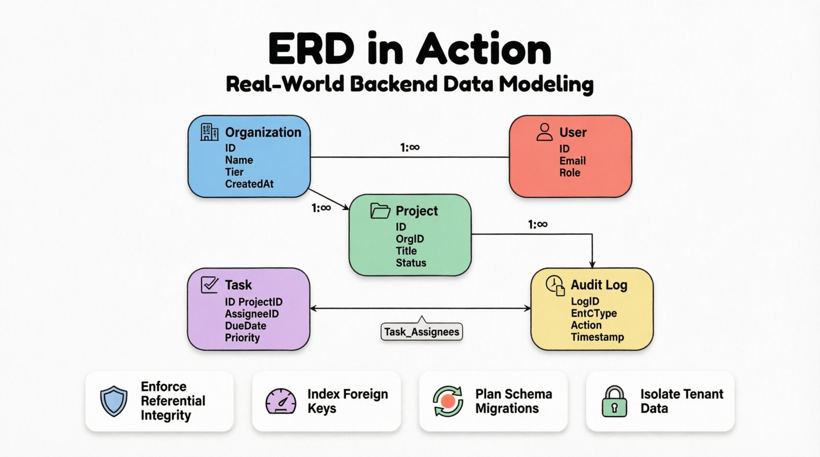
🔍 Core Entities and Attributes
The backbone of any ERD is the definition of entities. In this case study, we identify five primary entities. Each entity represents a distinct concept that must be persisted in the database. The attributes associated with these entities define the granularity of the data stored.
1. Organization Entity
This is the root of the hierarchy. Every other record is linked back to this entity to enforce tenant isolation.
- Organization ID: Unique identifier.
- Organization Name: Human-readable label.
- Subscription Tier: Determines feature access.
- Created At: Timestamp for auditing.
2. User Entity
Users belong to organizations but can be members of multiple projects. Authentication details are separated from business data to adhere to security best practices.
- User ID: Unique identifier.
- Email: Used for authentication and contact.
- Password Hash: Secure storage for credentials.
- Role: Defines permissions (Admin, Member, Viewer).
3. Project Entity
Projects are the containers for work items. They are owned by an organization but worked on by users.
- Project ID: Unique identifier.
- Organization ID: Foreign key linking to the parent tenant.
- Title: Short name for the project.
- Status: Active, Archived, or Deleted.
4. Task Entity
The core unit of work. This entity requires the most complex relationships as it links users, projects, and logs.
- Task ID: Unique identifier.
- Project ID: Foreign key.
- Assignee ID: Foreign key to User.
- Due Date: Temporal constraint.
- Priority: Enumerated value.
5. Audit Log Entity
Records every change made to critical entities. This ensures traceability.
- Log ID: Unique identifier.
- Entity Type: Which table was affected.
- Record ID: Which row was affected.
- Action: Create, Update, Delete.
- Performed By: User ID.
- Timestamp: Time of action.
🔗 Modeling Relationships and Cardinality
Relationships define how entities interact. In a production system, these relationships are enforced via foreign keys. The cardinality (one-to-one, one-to-many, many-to-many) determines how data is queried and updated.
Organization to User
This is a One-to-Many relationship. One organization can have many users, but a user record is tied to a single organization for data isolation purposes. To prevent data leakage between tenants, the organization_id is a mandatory foreign key on the User table.
Organization to Project
Similarly, this is a One-to-Many relationship. Projects cannot exist without a parent organization. If an organization is deleted, the cascade behavior must be carefully considered. In this case, we choose to soft-delete projects rather than hard-delete them to preserve historical context.
Project to Task
Another One-to-Many relationship. A project contains multiple tasks, and a task belongs to exactly one project. This is a standard structural link.
User to Task (Assignment)
This is the most critical relationship. A user can be assigned multiple tasks, and a task can be assigned to multiple users (collaborative work). This requires a Many-to-Many relationship.
To implement this, we introduce a junction table, often called an associative entity. This table breaks the many-to-many relationship into two one-to-many relationships.
| Table Name | Purpose | Keys |
|---|---|---|
| Task_Assignees | Links Users to Tasks | Task_ID, User_ID |
| Organization_Tenants | Links Organizations to Users | Organization_ID, User_ID |
Using a junction table allows us to store additional metadata. For example, in the Task_Assignees table, we might store the role the user had on that specific task (e.g., Lead, Contributor), which differs from their global user role.
⚖️ Constraints and Data Integrity
Application-level validation is not enough. Database constraints act as the final line of defense against data corruption. In a production environment, constraints should be defined at the schema level.
Referential Integrity
Foreign keys ensure that a record in a child table cannot reference a non-existent parent. For example, a task cannot be assigned to a user that does not exist in the system.
However, the ON DELETE and ON UPDATE behaviors are critical decisions:
- CASCADE: If a parent is deleted, all children are deleted. Use this for orphaned data that has no meaning without the parent (e.g., comments on a deleted post).
- RESTRICT: Prevents deletion if children exist. Use this to prevent accidental data loss (e.g., deleting an organization that has active billing records).
- SET NULL: If the parent is deleted, the foreign key column in the child becomes NULL. Use this when the relationship is optional.
Check Constraints
Standard SQL supports check constraints to enforce domain-specific rules. Examples include:
- Due Date: The
due_datecolumn must be greater than thecreated_atcolumn. - Priority: The
prioritycolumn must match a specific list of allowed values (e.g., Low, Medium, High). - Amount: Financial fields must be non-negative.
Unique Constraints
Ensure data uniqueness where required. For instance, an email address must be unique across the entire system, or within a specific organization depending on the user model. A composite unique constraint can ensure that a user is only assigned to a specific project once (preventing duplicate assignments).
🚀 Performance and Indexing Strategy
A well-designed schema is useless if queries are slow. Indexing is the mechanism that allows the database to find data quickly. However, indexes come with a cost in terms of write performance and storage.
Identifying Query Patterns
Before creating indexes, analyze the most common read operations. In our case study, typical queries include:
- Find all tasks assigned to a specific user.
- Find all projects within an organization.
- Retrieve audit logs for a specific entity ID.
Index Placement
Foreign keys are the most common candidates for indexing. If a query frequently filters by organization_id, an index on that column is mandatory. Without it, the database performs a full table scan, which degrades rapidly as data grows.
Composite indexes are useful for queries that filter on multiple columns. For example, if the system frequently searches for tasks by project_id AND status, a composite index on (project_id, status) is more efficient than two separate indexes.
Partial Indexes
In scenarios where only a subset of data is frequently queried, partial indexes save space. For example, if the system only queries for active tasks, an index that only includes rows where status = 'Active' can be significantly smaller and faster to traverse than an index on the whole table.
🛠️ Maintenance and Schema Evolution
Software requirements change. The database schema is no exception. Moving from version A to version B requires careful planning to avoid downtime and data loss. This process is often managed through migration scripts.
Adding Columns
Adding a new column is generally safe. If the column allows NULLs, existing rows are not affected. If the column requires a default value, ensure the default is applicable to all existing data to avoid constraint violations.
Removing Columns
Deleting a column is risky. It is better to mark the column as deprecated first. This allows developers to remove references to the column in the application code before physically removing it from the database. This two-phase approach prevents application errors during the deployment window.
Renaming Columns
Renaming columns is rarely supported in older database versions without complex workarounds. It is often better to add a new column with the desired name, migrate the data, and then remove the old column. This ensures the schema remains backward compatible during the transition.
🚧 Common Pitfalls in ERD Design
Even experienced architects make mistakes. Understanding common pitfalls helps in avoiding them during the design phase.
- Over-Normalization: Splitting data into too many small tables makes queries complex and slow. Balance normalization with query performance needs.
- Under-Normalization: Storing the same data in multiple places (e.g., repeating user names in every task log) leads to update anomalies. If a user changes their name, you must update every log entry.
- Circular Dependencies: Creating circular foreign key relationships can lead to deadlocks during insertion or deletion. Ensure the dependency graph is a Directed Acyclic Graph (DAG).
- Ignoring Soft Deletes: Hard deleting records removes history. Implement a
deleted_attimestamp column to keep records visible for auditing while hiding them from standard views. - Implicit Data Types: Using generic types like
VARCHAR(255)for everything wastes space. UseINTfor IDs,BOOLEANfor flags, and specific length constraints for strings where appropriate.
✅ Best Practices for Production ERDs
To ensure the longevity and health of the system, adhere to these guidelines:
- Document Relationships: The ERD itself is documentation. Ensure it is kept up to date with the actual schema. Automated tools can generate diagrams from the database to verify accuracy.
- Standardize Naming Conventions: Use
snake_casefor tables and columns. Prefix foreign keys with the relationship name (e.g.,organization_idinstead of justorg_id) for clarity. - Use UUIDs vs Auto-Increment: For distributed systems, UUIDs prevent collision issues when merging databases. For single-instance systems, auto-incrementing integers are more compact and faster.
- Plan for Growth: Design with partitioning in mind. If a table is expected to grow to billions of rows, consider how it will be split across shards or partitions based on the
organization_id. - Review Access Patterns: Regularly review slow query logs to identify missing indexes or inefficient joins.
🔄 The Lifecycle of a Schema
An ERD is not a static document. It evolves with the product. The lifecycle typically follows these stages:
- Design Phase: Drafting the initial model based on requirements.
- Implementation Phase: Creating migration scripts to build the schema.
- Validation Phase: Running load tests to verify performance assumptions.
- Iteration Phase: Adding new fields or relationships as features are added.
- Optimization Phase: Refining indexes and constraints based on production data.
During the optimization phase, you might discover that the initial cardinality assumptions were wrong. For example, you might find that a One-to-Many relationship was actually a Many-to-Many in practice, requiring a schema change to a junction table. This highlights the importance of flexibility in the design.
🛡️ Security Considerations in Schema Design
Data security is deeply intertwined with schema design. Row-Level Security (RLS) policies often rely on the structure of the ERD to function correctly. If the organization_id is not properly indexed and enforced, a user from Organization A might accidentally query Organization B’s data.
Furthermore, sensitive data should be separated. If the system handles payment information, that data should ideally reside in a separate schema or table with stricter access controls, rather than being mixed with general user metadata. This limits the blast radius in case of a breach.
📝 Summary of Design Decisions
The following table summarizes the key decisions made in this case study and the rationale behind them.
| Decision | Option A | Option B (Selected) | Rationale |
|---|---|---|---|
| Multi-Tenancy | Separate Databases | Shared Database, Shared Schema | Reduced operational overhead; easier to manage cross-tenant analytics. |
| Deleting Organizations | Hard Delete | Soft Delete | Preserves historical audit logs and prevents data loss for compliance. |
| Task Assignments | Single Column | Junction Table | Allows multiple assignees and tracks specific roles per assignment. |
| Primary Keys | Auto-Increment | UUIDs | Supports future distributed architecture and easier data merging. |
Building a production backend requires more than just writing code. It requires a deep understanding of how data flows and how it is structured. An ERD is the map that guides this journey. By following these principles, you ensure that the system remains stable, secure, and scalable as the business grows.
Remember, the goal is not to create the most complex diagram possible, but the one that best serves the application’s needs while minimizing technical debt. Continuous review and adaptation are key to maintaining a healthy data ecosystem.