Software engineering is not just about writing code; it is fundamentally about structuring thought. When developers move beyond syntax and into the architecture of a system, they require tools that represent reality, not just potential. This is where the object diagram becomes indispensable. Unlike the blueprint of a class diagram, an object diagram captures a specific moment in time—a snapshot of the running system. 📸
By visualizing instances, attributes, and relationships at a specific point in execution, engineers gain clarity on complex data flows. This guide explores how utilizing object diagrams refines your problem-solving skills, improves system stability, and aligns your mental model with the actual runtime state of your application.
Understanding the Object Diagram 🏗️
An object diagram is a static view of a system at a particular instant. In the Unified Modeling Language (UML), it complements the class diagram. While a class diagram defines the types of things that exist (the rules), an object diagram defines the instances of those things (the actual data).
Class vs. Object: The Distinction
Confusion often arises between these two modeling techniques. To think like an engineer, one must distinguish between the definition and the instantiation.
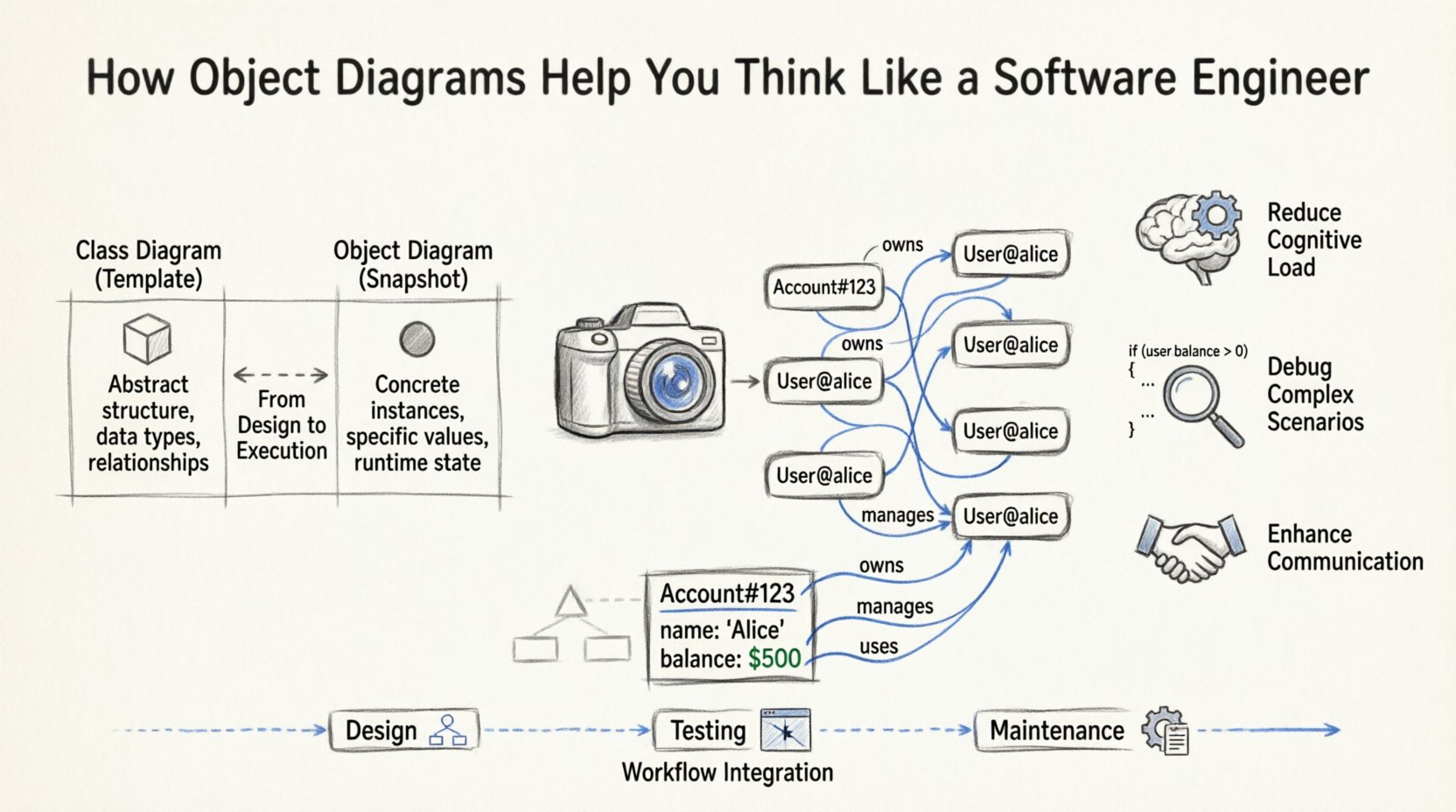
- Class Diagram: Represents the static structure. It shows classes, attributes, operations, and relationships (inheritance, association). It is the template.
- Object Diagram: Represents the dynamic state. It shows object instances, specific attribute values, and links between instances. It is the snapshot.
| Feature | Class Diagram | Object Diagram |
|---|---|---|
| Focus | Abstract Structure | Concrete Instances |
| Time | Permanent (Design Phase) | Temporary (Runtime State) |
| Attributes | Data Types (e.g., int, String) | Specific Values (e.g., 10, “Active”) |
| Links | Relationships (e.g., 1..* | Actual Connections |
| Usage | Architecture, Database Design | Debugging, Documentation, Testing |
Recognizing this distinction is the first step in adopting a rigorous engineering mindset. You stop thinking about what could happen and start analyzing what is happening.
The Cognitive Shift: From Abstract to Concrete 🔄
Programming involves high levels of abstraction. You write methods that handle generic inputs. However, bugs and performance issues often live in the specifics. Object diagrams force you to ground your thinking.
1. Visualizing Runtime State
When code executes, memory is allocated, and references are created. Tracing this mentally is difficult. An object diagram externalizes this memory state.
- Memory Allocation: You see exactly which objects occupy space.
- Reference Tracking: You visualize how Object A points to Object B.
- Null States: You identify where references are missing, preventing null pointer exceptions.
2. Reducing Cognitive Load
The human brain struggles to hold complex object graphs in working memory. By drawing the state:
- You offload information to the page.
- You reduce the need for mental rotation of data structures.
- You can spot cycles or orphaned nodes visually.
Practical Applications in Engineering 🛠️
The utility of object diagrams extends across the software development lifecycle. They are not merely academic exercises; they are practical tools for maintenance and design.
Debugging Complex Scenarios 🐛
When a system fails, logs often provide a trail of events. An object diagram helps reconstruct the state leading up to the failure.
- Tracing Data Flow: Map how a user input transforms into a database record.
- Identifying Circular Dependencies: See if Object A holds a reference to Object B, which holds a reference back to Object A, creating a loop.
- Memory Leaks: Visualize long-lived references that prevent garbage collection.
Designing Data Structures 🧩
Before writing code for complex algorithms, sketching the object state clarifies the requirements.
- Graph Algorithms: Visualize nodes and edges to ensure traversal logic is sound.
- Tree Structures: Confirm parent-child relationships and leaf node handling.
- Linked Lists: Verify head and tail pointers and next/prev references.
Documentation and Handover 📝
Code is the primary documentation, but it is dense. Object diagrams provide a high-level overview of the system’s state at critical junctures.
- New Team Members: They can see how instances interact without reading every line of code.
- API Contracts: Show the expected structure of response objects.
- Test Cases: Define the initial state required for unit tests.
Core Components of an Object Diagram 🧱
To construct these diagrams effectively, you must understand the specific elements involved. Precision is key to maintaining authority in your documentation.
- Object Instances: Represented as rectangles. The name is typically underlined to indicate it is an instance, not a class (e.g., customer_001).
- Attribute Values: Listed within the object rectangle. Unlike class diagrams that show types, these show current values (e.g., balance: $500.00).
- Links: Lines connecting objects. They represent associations between instances.
- Role Names: Labels on the links indicating the function of the connection (e.g., owns, manages).
- Multiplicity: While often implied by the connection, it indicates how many instances are involved (e.g., 1, 0..*).
Building Better Thinking Habits 🧠
Using these diagrams changes how you approach problems. It moves you from a reactive coder to a proactive architect.
1. Anticipating Edge Cases
When you draw the links between objects, you naturally ask: “What happens if this link is broken?” or “What if this object is null?” This anticipation leads to more robust code.
2. Simplifying Complexity
Complex systems are often decomposed into smaller object graphs. By isolating sub-graphs, you can solve problems in chunks rather than wrestling the entire system at once.
3. Enhancing Communication
Stakeholders often struggle with technical jargon. A diagram showing an order connected to a user and products is universally understood better than a stack trace.
| Thinking Habit | Without Object Diagrams | With Object Diagrams |
|---|---|---|
| Problem Analysis | Abstract reasoning | Concrete visualization |
| Debugging | Guessing state | Verifying state |
| Refactoring | Risk of breaking links | Safe restructuring |
| Team Sync | Verbal descriptions | Visual alignment |
Common Pitfalls to Avoid 🚫
Even with the best intentions, object diagrams can become cluttered or misleading. Avoid these common errors to maintain clarity.
- Overloading the Diagram: Do not include every single object in a large system. Focus on the specific scenario or module you are analyzing.
- Inconsistent Naming: Use clear, consistent naming conventions for instances. Ambiguity defeats the purpose of the diagram.
- Ignoring State Changes: Remember that an object diagram is a snapshot. If the state changes frequently, you may need multiple diagrams to tell the full story.
- Confusing Links with Methods: Links represent relationships, not function calls. Do not draw arrows for method invocations unless specifically modeling a sequence.
- Neglecting Attribute Values: The power of the object diagram lies in the values. If you only draw the structure, you have created a class diagram in disguise.
Integration into the Development Workflow 🔄
Integrating object diagrams into daily work requires discipline. They should not be an afterthought.
During Design Phase
Before coding, sketch the expected object graph. This ensures your database schema and class hierarchy support the runtime needs.
During Testing Phase
Use diagrams to define test fixtures. Draw the state you need to create before running the test logic.
During Maintenance Phase
When fixing a bug, update the diagram to reflect the current behavior. This keeps documentation synchronized with reality.
Advanced Concepts: Polymorphism and Inheritance 🏛️
Object diagrams can handle complex inheritance scenarios, which are crucial for object-oriented programming.
- Subtyping: An instance of a subclass is also an instance of its superclass. This must be reflected in the links.
- Interface Implementation: Show how objects implement specific behaviors, even if they come from different class hierarchies.
- Dynamic Binding: Visualize how the same link might point to different types of objects at runtime.
Understanding these nuances allows you to design flexible systems. You can model how a generic container holds specific items without knowing the exact type beforehand.
Conclusion on System Thinking 🎯
Adopting object diagrams is about more than drawing boxes and lines. It is about developing a disciplined approach to understanding state. By externalizing the invisible workings of memory and references, you reduce ambiguity and increase precision.
As you continue your engineering journey, incorporate these visualizations into your toolkit. They serve as a bridge between the abstract logic of algorithms and the concrete reality of deployed systems. This bridge is where robust software is built.
Start small. Pick a complex module in your current project. Draw the object state. You will likely find new insights that code alone obscured. This practice sharpens your mind, just as the tools sharpen your code.