Software development involves constructing systems that exist in the real world, yet operate within the logical constraints of code. While class diagrams provide the blueprint for structure, object diagrams reveal the actual state of that system at a specific moment. They serve as a snapshot of memory, capturing the relationships and data values that exist during execution. Many developers treat these diagrams as static illustrations, useful only for documentation or high-level presentations. However, their utility extends far beyond aesthetics.
Understanding the runtime state is critical for debugging, validation, and system architecture. An object diagram is not merely a picture; it is a model of reality. It bridges the gap between abstract design and concrete implementation. This guide explores the technical depth of object modeling, examining how these diagrams function as essential tools for engineering stability and clarity.
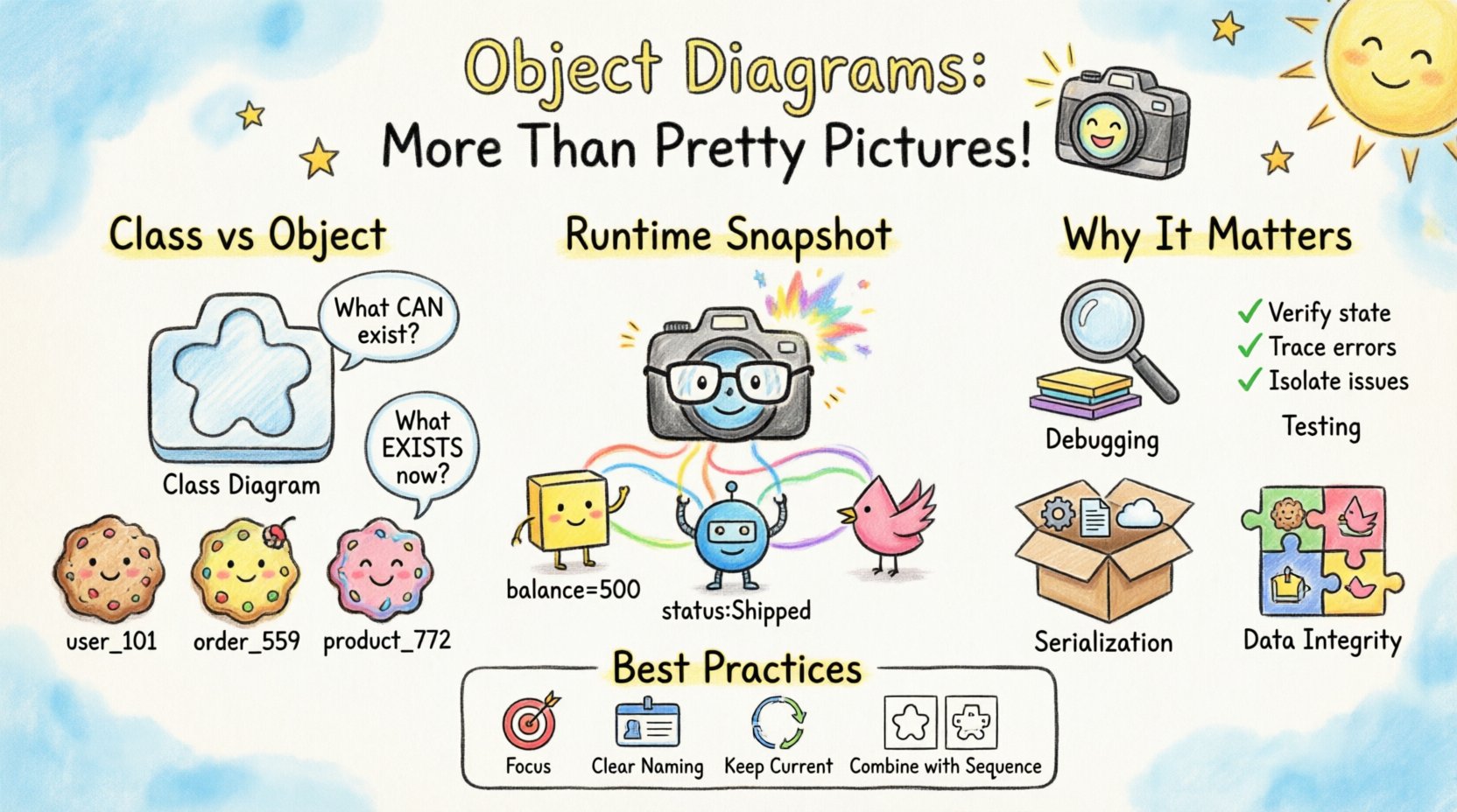
🧩 Understanding the Core Distinction: Class vs. Object
To appreciate the value of an object diagram, one must first distinguish it from its structural counterpart, the class diagram. A class diagram defines the template. It specifies types, attributes, operations, and general relationships like inheritance or aggregation. It answers the question: What can exist?
An object diagram defines an instance. It captures specific data values, active links, and the current configuration of the system. It answers the question: What exists right now?
- Class Diagram: Defines the blueprint. Static. Defines types (e.g.,
User,Order). - Object Diagram: Defines the snapshot. Dynamic. Defines instances (e.g.,
user_101,order_559).
Consider a simple banking application. The class diagram dictates that a BankAccount has an attribute balance of type decimal. The object diagram shows a specific account where balance = 500.00. This distinction is vital. A system can be structurally valid (all classes defined correctly) but logically invalid (objects in an impossible state). Object diagrams help visualize these logical states.
⚙️ The Runtime Reality: Snapshots of Memory
Software systems are dynamic. Data flows, connections are established and severed, and state changes constantly. An object diagram represents a frozen moment in this flow. This concept is particularly powerful when dealing with complex systems where the flow of data is non-linear.
📍 Capturing Linkages
In a class diagram, a relationship line might indicate that a Customer can have many Orders. In an object diagram, you see exactly which orders belong to which customer instance at the time of the snapshot. This is crucial for understanding data integrity. It reveals orphaned records, circular dependencies, or unintended references that the static blueprint does not expose.
- Instance Names: Objects are typically labeled with their class name and instance identifier (e.g.,
order:Order). - Attribute Values: Unlike class diagrams, object diagrams display actual values (e.g.,
status: "Shipped"). - Link Labels: Relationships can be labeled to indicate the specific role or direction of the connection at runtime.
🔄 Handling State Changes
When debugging a race condition or a concurrency issue, an object diagram can illustrate the state of shared resources. It allows engineers to visualize how multiple threads might interact with the same object instance. By mapping out these interactions, teams can identify potential bottlenecks before they manifest as production errors.
For example, if two processes attempt to update a InventoryItem simultaneously, an object diagram can show the intermediate state where the lock is held. This visualization aids in designing more robust synchronization mechanisms.
🛡️ Validation and Testing Strategies
One of the most underutilized functions of object diagrams is their role in validation. Before deploying code, developers can use these diagrams to verify that the expected data structures are being populated correctly. This process is often referred to as contract validation.
📋 Test Case Visualization
Instead of writing raw test code immediately, teams can sketch the expected object state. This serves as a visual specification for test cases.
- Pre-conditions: What objects must exist before a function runs?
- Post-conditions: What should the object graph look like after execution?
- Edge Cases: How do null values or empty collections appear in the instance graph?
This approach reduces ambiguity. A written requirement might say, “Ensure the user is logged in.” An object diagram specifies that the session object must exist and point to the user object with a specific token value. This precision minimizes the gap between requirements and implementation.
🧪 Regression Testing Support
During regression testing, object diagrams serve as a baseline. If a change in the codebase alters the internal structure of an object in an unexpected way, the diagram highlights the deviation. This is particularly useful in legacy systems where documentation is sparse. By reverse-engineering the runtime state into object diagrams, teams can understand the current architecture without relying solely on code inspection.
📦 Data Persistence and Serialization
Modern applications often rely on serialization to store data or transmit it across networks. Object diagrams are directly relevant here. When an object graph is serialized, the structure of the graph determines the structure of the serialized data (e.g., JSON, XML, or binary formats).
Understanding the object diagram helps in designing efficient data transfer objects (DTOs). If the object graph contains circular references, serialization will fail or require special handling. Visualizing the graph beforehand allows architects to break cycles or implement reference management strategies.
📊 Comparison: Object Diagram vs. Data Schema
| Aspect | Object Diagram | Data Schema (SQL/NoSQL) |
|---|---|---|
| Focus | Runtime Instance State | Storage Structure |
| Content | Actual values, specific links | Field types, constraints, keys |
| Changeability | Dynamic, changes per request | Static, defined at deployment |
| Usage | Debugging, Logic Validation | Database Design, Migration |
While a database schema defines the table structure, the object diagram defines how that data is connected in memory. A mismatch between the two can lead to performance issues, such as N+1 query problems, where the code retrieves data inefficiently because the object relationships were not modeled correctly.
🧱 Managing Complexity and Inheritance
Inheritance is a powerful feature in object-oriented programming, but it introduces complexity. A class diagram shows the hierarchy, but it does not show the concrete type of an instance at runtime. An object diagram clarifies this.
Consider a system with a base class Shape and subclasses Circle, Square, and Triangle. The class diagram shows that all inherit from Shape. The object diagram shows a specific instance: myShape: Circle. This distinction is critical for polymorphism.
- Type Safety: Object diagrams help verify that a variable holding a
Shapeactually contains a compatible subclass instance. - Method Resolution: By seeing the specific subclass, developers can determine which overridden methods will execute.
- Memory Footprint: Subclasses often add attributes. The object diagram can illustrate the cumulative size of an instance based on its concrete class.
When dealing with deeply nested inheritance hierarchies, object diagrams prevent confusion. They show exactly which attributes are active and which are inherited, ensuring that the logic aligns with the class structure.
🔍 Common Misconceptions and Pitfalls
Despite their utility, object diagrams are often misunderstood or misused. Recognizing these pitfalls ensures they remain effective tools rather than sources of confusion.
❌ Static vs. Dynamic Confusion
Many teams treat object diagrams as if they are static blueprints. They draw them once and never update them. This renders them obsolete quickly. Because software state changes, object diagrams must be treated as living documents, updated during key phases of development or when significant state changes occur.
❌ Over-Engineering
There is a temptation to model every single object in a large system. This leads to cluttered diagrams that are impossible to read. Object diagrams should focus on the critical path of the system. Focus on the objects involved in the specific feature or bug being analyzed, not the entire application graph.
❌ Ignoring Cardinality
Relationships in object diagrams must respect the cardinality defined in the class diagram. A common error is drawing a link that implies a one-to-many relationship when the instance data shows a many-to-many scenario. Consistency between the structural model and the instance model is non-negotiable.
🚀 Integration with Development Workflows
Integrating object modeling into the daily workflow requires discipline. It is not something that happens only during the design phase. It should be part of the review and debugging process.
📝 Code Reviews
During code reviews, reviewers can use object diagrams to trace the flow of data through the system. If a developer modifies an object’s attribute, the diagram helps visualize the downstream effects on other connected objects. This promotes a deeper understanding of system interdependencies.
🐞 Debugging Sessions
When a bug occurs, developers often dump logs. While logs show text, an object diagram shows structure. Visualizing the state at the point of failure can reveal issues that logs miss, such as a missing link or an unexpected null pointer that indicates a broken chain of references.
🔄 Documentation Maintenance
Documentation often becomes outdated. Object diagrams, being closer to the code than class diagrams, are easier to keep current. When code changes the instance behavior, the diagram is updated to reflect the new reality. This keeps the documentation aligned with the codebase.
🌐 Future Relevance in System Architecture
As systems become more distributed and microservices-based, the need for clear state management increases. Object diagrams remain relevant because they abstract away the network complexity and focus on the logical state of the data. Even in a distributed environment, understanding the local state of an object instance is fundamental to ensuring consistency.
Furthermore, with the rise of event-driven architectures, the state of an object changes in response to events. Object diagrams can map the state transitions triggered by these events, providing a clear view of the system’s reaction to external stimuli.
💡 Best Practices for Creation
To maximize the value of object diagrams, follow these guidelines:
- Focus on Relevance: Only include objects and links relevant to the specific problem or feature being discussed.
- Use Clear Naming: Instance names should be descriptive. Avoid generic names like
obj1orobj2. - Highlight Critical Data: Emphasize key attributes that define the state of the object, such as status flags or identifiers.
- Keep it Current: Update diagrams when the code logic changes significantly.
- Combine with Sequence Diagrams: Use sequence diagrams to show the flow of messages, and object diagrams to show the state at key points in that flow.
🔗 Conclusion
Object diagrams offer a window into the living system. They transform abstract classes into concrete realities, allowing engineers to see the data as it exists in memory. By moving beyond the static view of class diagrams, teams gain a deeper understanding of system behavior, data integrity, and runtime constraints.
When used correctly, these diagrams act as a communication bridge between design, development, and testing. They provide the clarity needed to navigate complex architectures and ensure that the software behaves as intended. Investing time in modeling object states pays dividends in reduced debugging time, fewer production errors, and a more maintainable codebase.
The power lies not in the drawing itself, but in the understanding it fosters. By treating object diagrams as functional tools rather than decorative artifacts, engineering teams can build systems that are robust, reliable, and aligned with their intended purpose.