Creating a robust software architecture begins with understanding the data and entities that populate it. While class diagrams provide the blueprint, object diagrams offer the snapshot. They depict specific instances of classes at a particular moment in time. This guide explores the mechanics of translating tangible, real-world objects into the structured language of UML object diagrams. We will move from abstract concepts to concrete visual representations without relying on specific tooling, focusing purely on the modeling principles.
🔍 Understanding the Foundation: What is an Object Diagram?
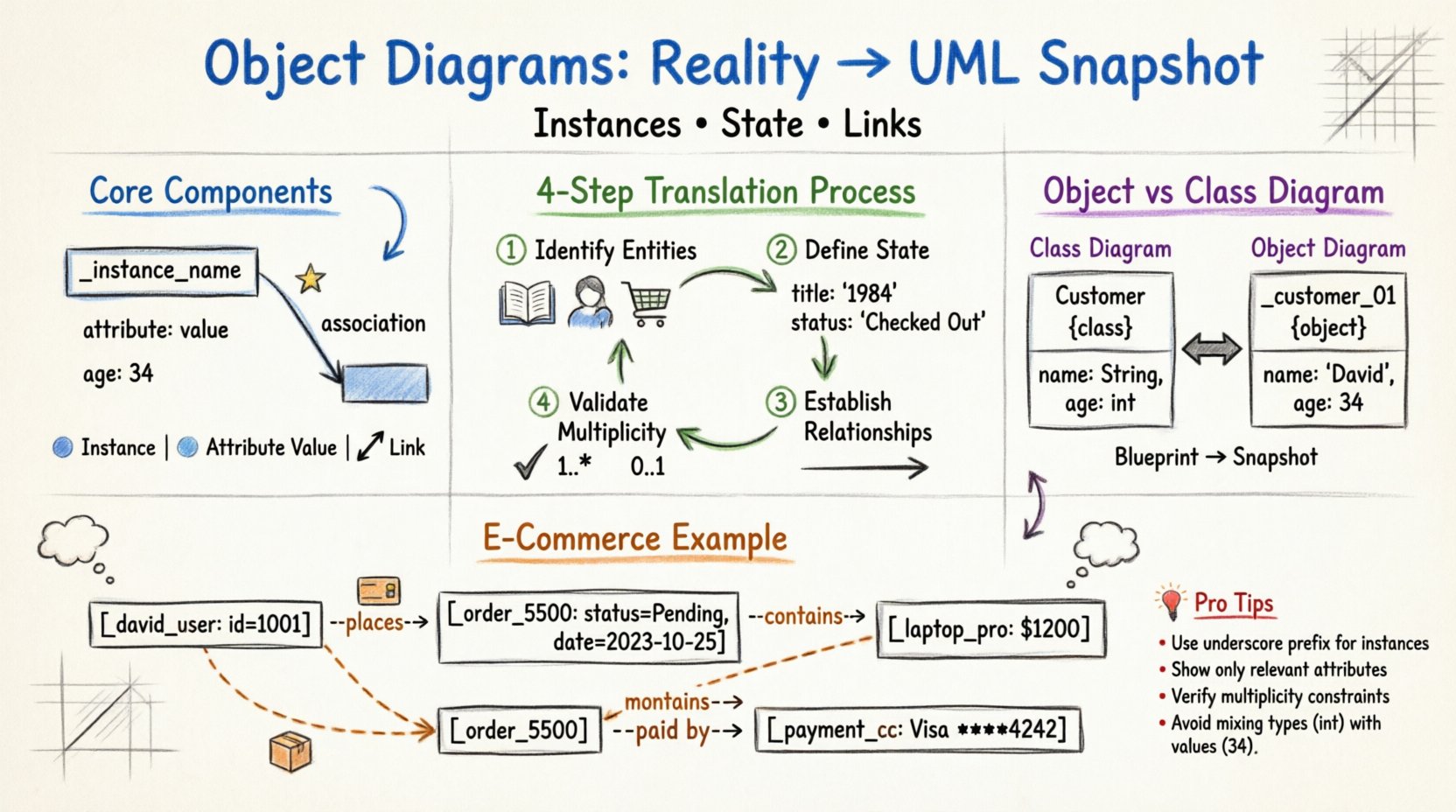
An object diagram is a static structure diagram in the Unified Modeling Language (UML). It represents a snapshot of the system at a specific point in time. Unlike a class diagram, which defines the types and behaviors available, an object diagram shows actual instances. It answers the question: “What data exists right now?”
- Instances: Concrete realizations of a class.
- State: The current values of attributes within those instances.
- Links: Relationships connecting instances to other instances.
When modeling a system, you often start with the domain. You identify people, places, things, and events. Translating these into an object diagram requires a disciplined approach to ensure the model reflects reality accurately. This process is crucial for validating system state before implementation begins.
🧱 Core Components of Object Modeling
To build a diagram, you must understand the visual syntax. Each element serves a specific purpose in conveying information about the system’s state.
1. Instances (Objects)
Objects are represented by rectangles. The top part of the rectangle contains the instance name, typically prefixed with an underscore (e.g., _john_doe or customer_01). This distinguishes them from class names, which are usually capitalized without prefixes. The bottom part lists the current attribute values.
2. Attributes and Values
In a class diagram, attributes show data types (e.g., age: int). In an object diagram, attributes show specific data values (e.g., age: 34). This shift from type to value is the defining characteristic of the object diagram.
- Primitive Types: Numbers, strings, booleans.
- Composite Types: Complex objects or collections.
- Null Values: Represented as empty or explicitly marked as
null.
3. Links (Associations)
Links represent the connections between objects. They are the runtime manifestation of associations defined in the class diagram. A link line connects two object rectangles. The line may have a label indicating the role or the type of relationship.
- Directionality: Some links are navigable, showing where information flows.
- Multiplicity: Cardinality constraints (e.g., 1..*, 0..1) dictate how many instances can be linked.
🔄 The Translation Process: From Reality to Diagram
Translating real-world scenarios into a diagram requires a systematic workflow. Skipping steps often leads to incomplete models that fail to capture critical business rules.
Step 1: Identify Entities
Start by listing the nouns in your scenario. If you are modeling a library system, entities include Book, Member, and LateFee. These map directly to classes. However, for an object diagram, you need specific instances.
- Question: Which specific books exist in the catalog right now?
- Question: Who are the active members?
Step 2: Define Current State
For each identified entity, determine its current state. A book is not just a generic entity; it has a specific title, an ISBN, and a status (e.g., “Available” or “Checked Out”).
- Object A: Title: The Great Gatsby, ISBN: 978-0…, Status: Available.
- Object B: Title: 1984, ISBN: 978-1…, Status: Checked Out.
Step 3: Establish Relationships
Now, connect the instances. If Object B is checked out, it must be linked to a Member instance. The relationship is a link. You must verify if the link adheres to the system rules defined in the design phase.
- Link: Member _alice_smith is associated with Book _book_1984.
- Constraint: Can a member have multiple books? Yes. Can a book be checked out by multiple members? No.
Step 4: Validate Multiplicity
Review the ends of your links. Do the connections match the multiplicity defined in the class model? If the class model says a Book can have 0 or 1 Loan, ensure your object diagram does not show a Book linked to two different Loans simultaneously.
📊 Practical Example: An E-Commerce Transaction
To illustrate the translation process, consider an online store processing a single order. We will translate the scenario into a visual model.
Scenario Description
A customer named David places an order for two items: a Laptop and a Mouse. The payment is processed via a CreditCard. The order status is currently Pending.
Object Identification
We extract the specific instances:
- Customer: _david_user (ID:
1001) - Order: _order_5500 (Date:
2023-10-25, Status:Pending) - Product 1: _laptop_pro (Price:
$1200) - Product 2: _mouse_wireless (Price:
$40) - Payment: _payment_cc (Type:
Visa, Last4:4242)
Linking the Objects
We draw connections to represent the flow of the transaction:
- _david_user places _order_5500.
- _order_5500 contains _laptop_pro.
- _order_5500 contains _mouse_wireless.
- _order_5500 is paid by _payment_cc.
This snapshot shows the exact state of the system. It does not define the rules for future orders, only the data present at this moment.
🆚 Object Diagram vs. Class Diagram
Confusion often arises between these two diagram types. While they share visual elements, their intent differs significantly. Understanding when to use which is vital for clear documentation.
| Feature | Class Diagram | Object Diagram |
|---|---|---|
| Focus | Types and Definitions | Instances and State |
| Timeframe | Static (Blueprint) | Snapshot (Current Moment) |
| Names | Class Names (e.g., Customer) | Instance Names (e.g., _customer_01) |
| Attributes | Data Types (e.g., int) |
Specific Values (e.g., 25) |
| Usage | System Design & Code Generation | Testing & Data Validation |
Use the class diagram to communicate the structure of the application to developers. Use the object diagram to communicate the data state to stakeholders or to verify logic during unit testing.
🛠️ Best Practices for Modeling
Creating diagrams is an art that requires discipline. Adhering to standards ensures that anyone reading the model understands it immediately.
1. Naming Conventions
Consistency prevents ambiguity. Adopt a standard for instance names.
- Prefix: Use an underscore (e.g.,
_) to denote instances. - Class Reference: Include the class name for clarity (e.g.,
_invoice_001vs_001). - Readability: Use lowercase for instance names to contrast with PascalCase class names.
2. Limit Scope
An object diagram is a snapshot. It does not need to show every single object in the system. Focus on a specific use case or scenario. Showing thousands of objects creates noise and hides the important relationships.
- Scenario A: Focus on a single login event.
- Scenario B: Focus on a completed purchase.
3. Attribute Visibility
Do not list every attribute if it is irrelevant to the current scenario. If an object has 50 attributes, but the scenario only involves 5, display only the 5. This reduces cognitive load.
4. Link Clarity
Links should be labeled if the relationship is complex. If multiple links exist between the same two objects, ensure role names are clear. Avoid crossing lines where possible to maintain readability.
⚠️ Common Pitfalls to Avoid
Even experienced modelers make mistakes. Being aware of common errors helps maintain model integrity.
1. Mixing Types and Values
A frequent error is placing data types in an object diagram. Attributes must show values. Writing age: int in an object diagram is incorrect. It should be age: 30.
2. Inconsistent Multiplicity
Ensure the number of links matches the defined constraints. If a class diagram specifies that a User has a maximum of one Profile, the object diagram must not show a User linked to three Profiles.
3. Isolated Objects
While some objects may be isolated (e.g., a configuration object), most objects in a functional scenario should be connected. If an object has no links, ask why it exists in this specific snapshot.
4. Over-Specification
Do not try to model the entire database history. An object diagram represents a point in time. Do not include historical data unless it is part of the current state (e.g., an audit log entry).
🔎 Deep Dive: Complex Associations
Sometimes, relationships are not simple one-to-one connections. They can be complex, involving multiple classes or conditional logic.
Aggregation in Object Diagrams
Aggregation represents a “whole-part” relationship where the part can exist independently. In an object diagram, this is shown with a diamond shape or a specific line style, depending on the notation standard.
- Example: A _department object contains multiple _employee objects.
- State: If the _department is deleted, the _employee objects may still exist.
Composition in Object Diagrams
Composition is a stronger form of association. The part cannot exist without the whole.
- Example: A _house object contains _room objects.
- State: If the _house is destroyed, the _room objects cease to exist in that context.
Recursive Links
Objects can sometimes link to themselves. This is common in hierarchical structures like organizational charts or file systems.
- Example: A _manager object is linked to another _manager object representing their supervisor.
- Visual: A line loops from the object back to itself.
📝 Writing the Model Documentation
A diagram is rarely standalone. It usually accompanies textual descriptions. When documenting your object diagram, include the following:
- Context: What scenario is this diagram representing?
- Time: When does this state occur? (e.g., “After checkout, before shipping”).
- Assumptions: What data is assumed to be present but not shown?
- Legend: If you use custom symbols, explain them.
This documentation ensures that the diagram remains useful over time. Without context, a diagram becomes a static image with no narrative.
🚀 Conclusion on Modeling
Translating real-world objects into object diagrams is a critical skill for system analysis. It forces clarity on data states and relationships that might otherwise remain abstract. By focusing on instances, values, and links, you create a tangible representation of the system’s behavior.
Remember that the goal is communication. Whether you are discussing a potential bug with a developer or explaining a feature to a client, the object diagram provides a common ground. It bridges the gap between the abstract logic of code and the concrete reality of user interaction.
Adopt the discipline of consistent naming, strict adherence to multiplicity, and clear visual representation. As you practice, the translation from concept to diagram will become intuitive, allowing you to focus on the architecture rather than the syntax.