Software architecture relies heavily on precise modeling to ensure that complex systems function as intended. Among the various diagrams used in the Unified Modeling Language (UML), the Object Diagram holds a unique position. It provides a snapshot of the system at a specific moment in time, detailing instances of classes and their relationships. While Class Diagrams define the structure, Object Diagrams validate the runtime behavior and data integrity.
Errors within these diagrams can lead to significant downstream issues, including code generation failures, runtime exceptions, and misalignment between design and implementation. This guide provides a deep dive into identifying and resolving common issues found in object modeling. By addressing these problems early, teams can maintain a high standard of system integrity and avoid costly rework.
🧐 Why Object Diagram Errors Matter
Object diagrams are not merely static illustrations; they represent the actual state of data flowing through the application. When an error exists in an object diagram, it suggests a fundamental flaw in how the system handles instances. These flaws often stem from misinterpretations of class definitions, incorrect relationship mappings, or overlooked lifecycle constraints.
Consider the following scenarios where diagram errors cause project delays:
- Runtime Crashes: If an object instance is defined with attributes that do not exist in the class, the compiler or runtime environment may fail to initialize the object correctly.
- Logic Flaws: Incorrect multiplicity (e.g., defining a one-to-many relationship as one-to-one) leads to data loss or overflow during execution.
- Integration Failures: When multiple teams work on different parts of a system, inconsistent object modeling creates incompatibility at the integration stage.
- Maintenance Debt: Unclear or erroneous diagrams make future modifications difficult, as developers cannot trust the existing model.
Addressing these issues requires a systematic approach to validation and debugging. The following sections outline the specific categories of errors and the methodologies used to resolve them.
📐 Structural and Syntax Errors
The foundation of any object diagram lies in its structural integrity. This involves ensuring that every instance correctly references a valid class and that the attributes assigned to those instances match the class definition. Structural errors are often the easiest to detect but the most damaging if ignored.
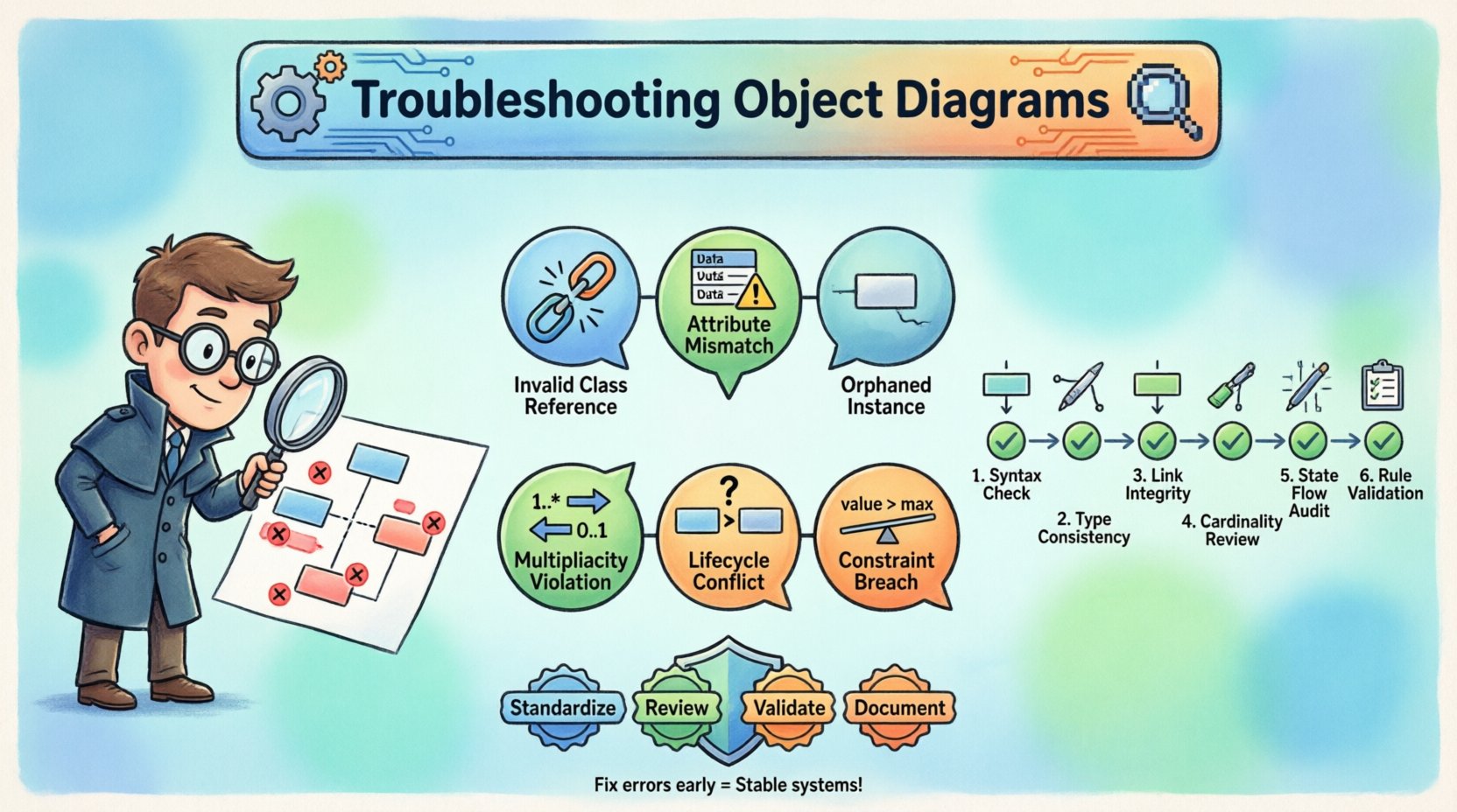
1. Invalid Class References
Every object instance must belong to a specific class. An error occurs when an instance is linked to a class that does not exist within the current system model. This can happen due to:
- Typographical errors in class names.
- Missing class definitions in the package structure.
- Incorrect namespace or scope resolution.
To troubleshoot this, verify the spelling of every class name associated with an instance. Cross-reference the instance against the master class repository. If a class is removed or renamed, all dependent object instances must be updated immediately to maintain consistency.
2. Attribute Mismatches
Attributes define the data held by an object. An error arises when an instance contains an attribute that is not defined in its parent class, or when the data type of an attribute is incompatible. For example, assigning a text string to an integer field will cause validation failures.
Common attribute errors include:
- Missing Attributes: The instance displays a field that the class does not support.
- Type Mismatches: Numeric values placed in string fields, or null values where mandatory fields are expected.
- Visibility Violations: Attempting to display private attributes in an external object view without proper accessor methods.
Resolution involves auditing the class definition and ensuring every instance adheres strictly to the schema. Use validation tools or manual checklists to compare instance data against class metadata.
3. Orphaned Instances
An orphaned instance is an object that exists in the diagram but has no valid association with other objects or the main system context. While sometimes intentional for testing purposes, in a production design, these can indicate incomplete logic.
Signs of orphaned instances:
- No incoming or outgoing links (associations) to other objects.
- Disconnected from the root object or entry point of the system.
- Isolated data that cannot be accessed by the application flow.
Fixing orphaned instances requires tracing the data flow. Determine if the object is necessary for the current state. If it is, establish the correct links. If it is obsolete, remove it from the diagram to maintain clarity.
⚙️ Semantic and Logic Issues
Structural errors are visible at a glance, but semantic errors are deeper. These relate to the meaning and logic behind the relationships and constraints. They often require a deeper understanding of the business rules and system behavior.
1. Multiplicity Violations
Multiplicity defines how many instances of one class can be associated with one instance of another class. Common notations include 0..1, 1..*, or 1..1. Errors here occur when the diagram depicts a relationship that violates these constraints.
Examples of multiplicity errors:
- Over-association: Linking a single user instance to more orders than allowed by the 1..* constraint.
- Under-association: Showing an order instance with no items when the constraint requires at least one item (1..*).
- Cardinality Confusion: Confusing one-to-one with one-to-many relationships, leading to data duplication or loss.
To resolve this, review the association lines and their labels. Ensure that the visual representation matches the defined cardinality. If the business rule changes, update the diagram immediately to reflect the new reality.
2. Lifecycle and State Conflicts
Objects often have a lifecycle, moving from creation to active use to deletion. An object diagram implies a specific state. If an object is shown in a state it cannot legally occupy, the diagram is invalid.
Common lifecycle errors:
- Active on Deleted Objects: Showing an instance that has been marked as deleted in the class logic.
- Uninitialized States: Displaying an object as active before its required constructor arguments are provided.
- State Machine Violations: Transitioning an object between states without passing through intermediate required states.
Validation requires mapping instances to state diagrams. Ensure that every object shown exists in a valid state within the system’s logic. This often involves consulting the state machine diagrams or documentation for each class.
3. Constraint Violations
Constraints are rules that limit the behavior of the system. They can be mathematical, logical, or temporal. Violating a constraint in an object diagram suggests the data is invalid.
Examples:
- Range Errors: An age attribute set to 200 years.
- Uniqueness Constraints: Two instances sharing the same primary key where uniqueness is enforced.
- Dependency Errors: An object depending on another object that does not exist in the current snapshot.
Fixing constraint violations requires data validation. Check every value against the defined constraints in the class specification. If the data is invalid, it must be corrected or the constraint relaxed if the business rule has changed.
🔍 A Step-by-Step Validation Workflow
To effectively troubleshoot object diagrams, teams should adopt a standardized workflow. This ensures consistency and reduces the chance of overlooking errors. The following process can be applied to any modeling effort.
- Inventory Check: List all classes and instances present in the diagram. Ensure no duplicates exist.
- Reference Audit: Verify every instance points to a valid class definition.
- Attribute Verification: Check that all attribute values match the expected data types and constraints.
- Relationship Mapping: Trace every association line to ensure it meets multiplicity requirements.
- State Consistency: Confirm that no object is in an impossible state.
- Context Review: Ensure the diagram represents a valid snapshot of the system at a specific point in time.
This workflow should be repeated whenever the model changes. Regular validation prevents errors from accumulating over the life of the project.
📉 Impact on Development and Deployment
Ignoring errors in object diagrams has tangible consequences for the development lifecycle. When models are flawed, the code generated or written based on those models inherits those flaws.
Development Impacts:
- Increased Debugging Time: Developers spend hours tracing errors back to the design level.
- Refactoring Costs: Significant rework is required to fix architecture that was flawed from the start.
- Testing Complexity: Unit tests may fail because the object structure does not match the test expectations.
Deployment Impacts:
- System Instability: Runtime errors occur due to missing or mismatched object definitions.
- Data Corruption: Invalid relationships lead to data being stored incorrectly in the database.
- Security Risks: Improper object modeling can expose vulnerabilities, such as unauthorized access to attributes.
Investing time in troubleshooting diagrams upfront saves significant resources later. It is a proactive measure rather than a reactive one.
🛡 Prevention Strategies and Best Practices
While troubleshooting is necessary, prevention is preferable. Implementing best practices during the initial design phase reduces the likelihood of errors.
1. Standardize Notation
Ensure all team members use the same UML standards. Consistency in naming conventions, arrow styles, and multiplicity notation reduces confusion and errors.
2. Enforce Code Reviews
Treat object diagrams as code. Include them in peer review processes. A second set of eyes can often spot semantic errors that the designer missed.
3. Use Validation Tools
Leverage automated tools that check for structural and semantic consistency. While human judgment is essential, automation can catch syntax and basic constraint errors instantly.
4. Maintain Documentation
Keep documentation updated alongside the diagrams. If a business rule changes, the diagram and the documentation must change simultaneously.
📊 Common Error Categories and Solutions
The table below summarizes the most frequent errors encountered in object modeling and the recommended actions to resolve them.
| Error Category | Typical Symptom | Root Cause | Solution |
|---|---|---|---|
| Invalid Class Reference | Instance points to unknown class | Typo or missing class | Verify class registry and spelling |
| Attribute Mismatch | Data type conflict | Incorrect value assignment | Check class schema and constraints |
| Multiplicity Violation | Too many or too few links | Incorrect relationship definition | Review association cardinality |
| Orphaned Instance | Disconnected object | Incomplete logic flow | Link to parent or remove if unused |
| State Conflict | Impossible state transition | Lifecycle misunderstanding | Align with state machine rules |
| Constraint Breach | Invalid data value | Business rule ignored | Apply validation rules to data |
👥 Collaborative Debugging
Object diagrams often serve as a communication tool between different roles, such as architects, developers, and business analysts. Discrepancies often arise when these groups interpret the diagram differently.
Tips for collaboration:
- Shared Vocabulary: Ensure everyone agrees on terminology (e.g., what constitutes an “instance” vs a “object”).
- Visual Walkthroughs: Conduct sessions where the diagram is walked through step-by-step with the team.
- Feedback Loops: Encourage team members to flag potential errors during the design phase.
This collaborative approach ensures that the diagram is not just technically accurate but also aligned with business expectations.
🔄 Long-term Maintenance
Systems evolve. New features are added, and old ones are retired. Object diagrams must evolve with the system. A diagram that was accurate six months ago may be obsolete today.
Maintenance Checklist:
- Update diagrams after every major release.
- Archive old versions for historical reference.
- Review diagrams during sprint planning sessions.
- Remove deprecated instances immediately.
By treating the diagram as a living document, teams ensure that troubleshooting remains a manageable task rather than a crisis.
🧩 Advanced Troubleshooting Scenarios
Some scenarios require more nuanced troubleshooting. These often involve complex inheritance hierarchies or dynamic object creation.
1. Inheritance and Polymorphism
When dealing with subclasses, an instance might belong to a parent class but exhibit properties of a child. Errors occur when the diagram does not clearly distinguish between the two. Ensure that inherited attributes are correctly represented and that specific child instances are labeled appropriately.
2. Dynamic Associations
Some systems create relationships at runtime rather than design time. Diagramming these requires showing the potential for dynamic links. Avoid hardcoding specific instances if the relationship is flexible. Use generic placeholders to indicate potential connections.
3. Distributed Systems
In distributed environments, objects may reside on different nodes. An object diagram must account for network latency or data synchronization issues. Ensure that the diagram reflects the consistency requirements of the distributed architecture.
🎯 Summary of Key Actions
To maintain the integrity of your system design, focus on the following actions:
- Regularly audit instances against class definitions.
- Validate all relationships and multiplicity constraints.
- Ensure state consistency across all objects.
- Incorporate diagram review into the development workflow.
- Keep documentation synchronized with the visual models.
By adhering to these principles, teams can minimize errors and ensure that the object diagrams serve as reliable blueprints for the software being built. Accuracy in modeling translates directly to stability in the final product.
🔗 Final Thoughts on Model Integrity
The effort invested in troubleshooting object diagrams pays dividends throughout the project lifecycle. A clean, accurate model reduces ambiguity, facilitates communication, and prevents technical debt. While the process requires diligence, the alternative is a system built on shaky foundations.
Remember that diagrams are tools for thought. They help us understand the system before we build it. When they are flawed, our understanding is flawed. Take the time to fix errors now, and the path to deployment will be smoother. Continuous validation ensures that the model remains a true reflection of the system’s reality.