3 语言结构
本章描述了ArchiMate企业架构建模语言的结构。其标准元素和关系的详细定义及示例将在第4章至第1章中介绍
3.1 语言设计考虑
在开发企业架构通用元模型的过程中,一个关键挑战是在特定领域语言的精确性与一套非常通用的架构概念之间取得平衡,后者反映了将系统视为一系列相互关联实体的观点。
ArchiMate语言的设计始于一组相对通用的概念。这些概念已在后续章节中说明,针对不同架构层级进行了专门化应用。该语言最重要的设计限制是,它被明确设计为尽可能小,但仍能满足大多数企业架构建模任务的需求。许多其他语言试图满足所有潜在用户的需求。为了便于学习和使用,ArchiMate语言仅限于足以建模所谓80%实际案例的概念。
本标准并未详细说明ArchiMate语言设计背后的详细理由。感兴趣的读者可参考[1]、[2]和[3],其中详细描述了语言构建及设计考虑因素。
3.2 顶层语言结构
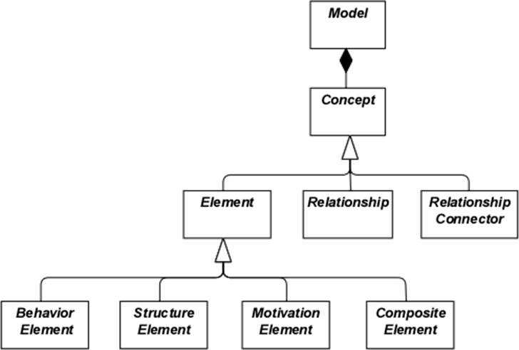
- 模型是一组概念——一个概念要么是元素,要么是关系
- 元素可以是行为元素、结构元素、动机元素或复合元素
请注意,这些是抽象概念;它们并非直接用于模型中。为表示这一点,它们以白色呈现,标签使用斜体。有关图1中所用符号的解释,请参见第4章。
3.3 ArchiMate语言的分层
ArchiMate核心语言定义了一组通用元素及其关系的结构,这些可在不同层级中进行专门化。ArchiMate核心语言中定义了以下三个层级:
- 业务层描述了向客户提供的业务服务,这些服务由业务角色执行的业务流程在组织中实现。
- 应用层描述了支持业务的应用服务及其实现这些服务的应用程序。
- 技术层包含信息技术和运营技术。例如,您可以建模处理、存储和通信技术以支持应用层和业务层,也可以通过设施、物理设备、材料和分销网络来建模运营或物理技术。
不同层中模型的总体结构相似。使用相同类型的元素和关系,尽管它们的具体性质和粒度有所不同。在下一章中将介绍通用元模型的结构。在第8章、第9章和第10章中,这些元素将被具体化,以获得特定层特有的元素。
与服务导向一致,层之间最重要的关系是由“服务”关系形成的[1]关系,展示一个层中的元素如何被其他层的服务所支持。(然而请注意,服务不仅可支持另一层的元素,也可以支持同一层的元素。)第二种链接由实现关系构成:下层的元素可以实现上层的对应元素;例如,一个
“数据对象”(应用层)可以实现一个“业务对象”(业务层);或者一个
“构件”(技术层)可以实现“数据对象”或“应用组件”(应用层)。
3.4 ArchiMate 核心框架
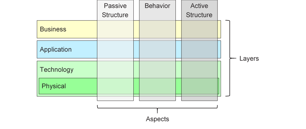
ArchiMate 核心框架是一个由九个单元组成的框架,用于对 ArchiMate 核心语言的元素进行分类。它由三个方面和三个层组成,如图2所示。这被称为 ArchiMate 核心框架。
重要的是要理解,基于方面和层对元素进行分类仅是一种总体分类。现实中的架构元素不必严格局限于某一特定方面或层,因为连接不同方面和层的元素在连贯的架构描述中起着核心作用。例如,提前讨论后续的概念性内容,业务角色作为“纯行为性”元素与“纯结构性”元素之间的中介元素,而某个软件是否被视为应用层或技术层的一部分,可能取决于具体上下文。
该框架的结构允许从不同视角对企业进行建模,其中单元格中的位置突出了利益相关者的关注点。利益相关者通常可能关注多个单元格。
- 层——ArchiMate 中企业可以建模的三个层次——业务层、应用层和技术层(如第3.3节所述)
- 方面:
— 主动结构方面,代表结构元素(展示实际行为的业务参与者、应用组件和设备;即行为的“主体”)
— 行为方面,代表行为(流程、功能、事件和服务);结构元素被分配给行为元素,以表明谁或什么展示了该行为
— 被动结构方面,代表行为作用的对象;这些通常是业务层的信息对象和应用层的数据对象,但也可能用于表示物理对象
这三个方面受到自然语言的启发,因为一个句子包含主语(主动结构)、谓语(行为)和宾语(被动结构)。通过使用人们在其母语中熟悉的相同构造,ArchiMate 语言更容易学习和阅读。
由于 ArchiMate 符号是一种图形化语言,其中元素按空间组织,因此这种顺序在建模中并不重要。
复合元素,如图1所示,是一种不一定局限于框架中单一方面(列)的元素,而可能结合两个或多个方面。
请注意,ArchiMate 语言并不要求建模者使用任何特定的布局,例如本框架的结构;它仅仅是对语言元素的分类。
3.5 ArchiMate 完整框架
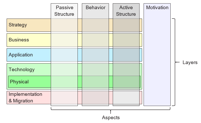
本标准版本所述的 ArhiMate 完整框架在核心框架的基础上增加了若干层和一个方面。物理元素被包含在技术层中,用于对物理设施、设备、分发网络和材料进行建模。因此,这些元素也是核心元素。战略元素被引入以建模战略方向和选择,相关内容在第7章中描述。动机方面在下一章以通用形式引入,并在第6章中详细说明。实施与迁移元素在第12章中描述。由此产生的 ArhiMate 完整框架如图3所示。
ArchiMate 语言并未为信息定义特定的层;然而,被动结构方面的元素,如业务对象、数据对象和工件,被用来表示信息实体。信息建模在 ArhiMate 的不同层级中均得到支持。
3.6 ArchiMate 语言中的抽象
ArchiMate 语言的结构支持几种常见的抽象与细化形式。首先,外部(黑箱,从盒子内容中抽象)与内部(白箱)视图之间的区别在系统设计中十分常见。外部视图描述系统对环境所必须完成的任务,而内部视图则描述系统如何完成这些任务。
其次,行为与主动结构之间的区别常被用来将系统必须完成的任务及其执行方式,与执行这些任务的系统构成要素(人员、应用程序和基础设施)区分开来。在建模新系统时,通常从系统必须执行的行为开始较为有利;而在建模现有系统时,通常从构成系统的人员、应用程序和基础设施入手,再详细分析这些主动结构所执行的行为。
第三种区别是概念、逻辑和物理抽象层级之间的差异。这一区分源于数据建模:概念元素代表业务认为相关的数据;逻辑元素为这些信息提供逻辑结构,以便信息系统进行处理;物理元素描述这些信息的存储方式,例如以文件或数据库表的形式。在 ArhiMate 语言中,这对应于业务对象、数据对象和工件,以及它们之间的实现关系。
逻辑元素与物理元素之间的区别也被应用于应用程序的描述中。TOGAF 企业元模型[4]包含一组实体,用于描述业务、数据、应用和科技组件及服务,以表达架构概念。逻辑组件是与实现或产品无关的数据或功能封装,而物理组件则是有形的软件组件、设备等。这一区别在 TOGAF 框架中以架构构建块(ABBs)和解决方案构建块(SBBs)的形式体现。这一区别在将企业架构从高层次的抽象描述推进到具体的实现级设计时依然具有重要意义。请注意,构建块可能包含多个元素,这些元素通常使用 ArhiMate 语言中的分组概念进行建模。
ArchiMate 语言提供了三种建模此类抽象的方式。首先,如[6]所述,行为元素(如应用功能和技术功能)可用于建模逻辑组件,因为它们代表了与实现无关的功能封装。相应的物理组件则可通过分配给行为元素的主动结构元素(如应用组件和节点)进行建模。其次,ArchiMate 语言支持实现的概念。这最好通过自技术层向上进行说明。技术层定义了实现应用组件的物理工件和软件,同时也提供了与实现信息系统所需其他物理概念(如设备、网络等)的映射。实现关系还可用于建模更抽象的实现关系,例如在(更具体)需求与(更通用)原则之间,需求的满足意味着对原则的遵循。实现关系也允许存在于应用组件之间以及节点之间。这样,可以分别建模物理应用或技术组件实现逻辑应用或技术组件。第三,逻辑和物理应用组件可被定义为应用组件元素的元模型级别特化,如第14章所述(另见14.2.2节中的示例)。TOGAF 内容元模型中的逻辑和物理技术组件也以相同方式定义为节点元素的特化(参见14.2.3节)。
ArchiMate 语言有意不支持类型与实例之间的区别。在企业架构的抽象层次上,更常见的是建模类型和/或示例,而非实例。同样,ArchiMate 语言中的业务流程并不描述一个具体的实例(即该流程的一次执行)。因此,在大多数情况下,使用业务对象来建模对象类型(参见一个UML®类),组织内可能存在多个此类实例。例如,每次保险申请流程的执行可能会产生一个具体的保险保单业务对象实例,但这一实例在企业架构中并未被建模。
3.7 概念及其表示法
ArchiMate 语言将语言概念(即元模型的构成要素)与其表示法分离开来。不同的利益相关者群体可能需要不同的表示法,以便理解架构模型或视图。在这方面,ArchiMate 语言与 UML 或 BPMN™ 等语言不同,后者仅有一种标准化的表示法。第13章中解释的视角机制提供了定义此类面向利益相关者的可视化方法。
尽管 ArchiMate 概念的表示法可以(并且应当)针对不同利益相关者进行定制,但本标准提供了一种通用的图形表示法,可供架构师及其他 ArchiMate 模型开发者使用。该表示法面向熟悉现有技术建模方法(如实体关系图 ERD、UML 或 BPMN)的受众,因此与其相似。在本文档其余部分,除非另有说明,用于表示语言概念的符号均代表 ArchiMate 标准表示法。大多数元素的标准表示法为右上角带有一个图标的小方框。在某些情况下,该图标本身也可作为替代表示法使用。应尽可能优先使用这种标准图示,以便任何熟悉 ArchiMate 语言的人都能读懂该语言生成的图表。
3.8 嵌套的使用
将元素嵌套在其他元素内部,可作为表达某些关系的替代图形表示法。这在第5章以及每种关系的定义中均有详细说明。
3.9 颜色与符号提示的使用
在本标准中的元模型图示中,使用灰色的深浅来区分属于 ArhiMate 框架不同方面的元素,具体如下:
- 白色:抽象(即不可实例化)概念
- 浅灰色:被动结构
- 中灰色:行为
- 深灰色:主动结构
在 ArhiMate 模型中,颜色没有正式的语义定义,颜色的使用由建模者自行决定。然而,它们可以自由用于强调模型中的某些方面。例如,在本标准展示的许多示例模型中,颜色被用来区分 ArhiMate 核心框架的各层,具体如下:
它们也可用于视觉强调。推荐参考文献[1]的第6章以获取相关指导。除了颜色外,还可使用其他符号提示来区分框架的各层。元素左上角的字母 M、S、B、A、T、P 或 I 可分别表示动机、战略、业务、应用、技术、物理或实施与迁移元素。该表示法的示例见示例34。
标准符号还使用一种约定,即通过符号角的形状来表示不同元素类型,具体如下:
- 方形角用于表示结构元素
- 圆角用于表示行为元素
- 对角线角用于表示动机元素
[1]请注意,此名称在标准的早期版本中被称为“被使用”。为便于理解,现已更改为“服务”。