数据库设计中架构成熟度的重要性
实体关系图(ERD)是有效系统架构的基石。它们并非静态的图示,而是在三个不同的阶段逐步构建的架构成熟度。每个阶段在数据库设计生命周期中发挥着独特的作用,服务对象从利益相关者到数据库管理员不等。尽管这三个层级都包含实体、属性和关系,但其细节深度和技术具体性存在显著差异。
要真正理解这些模型的演进过程,使用建筑类比会很有帮助。想象一下建房子:一个概念ERD是建筑师最初的草图,展示厨房和客厅等房间的大致位置。而逻辑ERD是详细的平面图,明确标注尺寸和家具摆放位置,但尚未规定具体材料。最后,物理ERD则作为工程蓝图,明确标注精确的管道布局、电气布线以及地基所用的具体品牌混凝土。
1. 概念ERD:业务视角
这个概念ERD代表了最高层次的抽象。它提供了业务对象及其关系的战略性视图,不包含任何技术杂乱信息。
目的与重点
该模型主要用于需求收集以及可视化整体系统架构。其主要目标是促进技术团队与非技术利益相关者之间的沟通。它关注于定义存在哪些实体——例如“学生”、“产品”或“订单”——而不是这些实体将在数据库表中如何实现。
细节层次
概念模型通常缺乏技术约束。例如,多对多关系通常仅作为关系呈现,而不涉及基数或连接表的复杂性。独特的是,这一层级可能使用泛化,例如将“三角形”定义为“形状”的子类型,这一概念在后续的物理实现中会被抽象掉。
2. 逻辑ERD:详细视图
随着成熟度等级的降低,逻辑ERD它作为概念模型的增强版本,弥合了抽象业务需求与具体技术实现之间的差距。
目的与重点
逻辑模型将高层次的需求转化为操作性和事务性实体。虽然它定义了明确的列每个实体的列,但它仍然严格独立于特定的数据库管理系统(DBMS)在这个阶段,最终数据库是使用Oracle、MySQL还是SQL Server并不重要。
详细程度
与概念模型不同,逻辑ERD为每个实体都包含属性。然而,它并未详细说明诸如数据类型(例如整数与浮点数)或特定字段长度等技术细节。
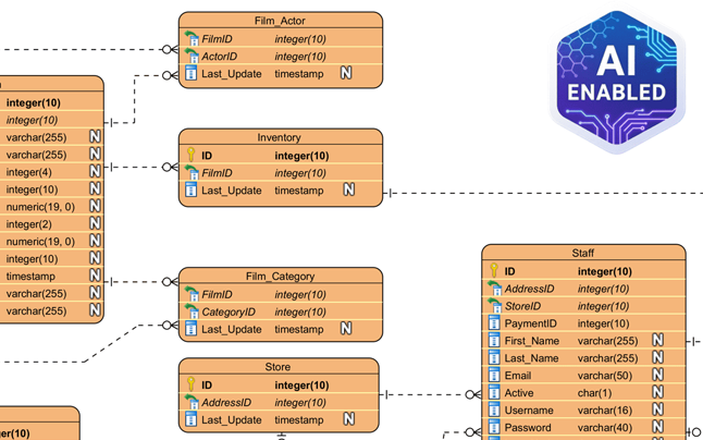
3. 物理ERD:技术蓝图
该物理ERD它代表了关系型数据库的最终可执行技术设计。它是将被部署的模式。
目的与重点
该模型作为在特定DBMS中创建数据库模式的蓝图。它通过分配具体的数据类型、长度和约束(例如varchar(255), int,或可为空).
详细程度
物理ERD非常详细。它定义了精确的主键(PK)以及外键 (FK)以严格强制关系。此外,还必须考虑目标数据库管理系统(DBMS)的特定命名约定、保留字和限制。
ERD 模型的比较分析
为了总结这些架构层级之间的区别,下表概述了不同模型中通常支持的功能:
| 功能 | 概念 | 逻辑 | 物理 |
|---|---|---|---|
| 实体名称 | 是 | 是 | 是 |
| 关系 | 是 | 是 | 是 |
| 列/属性 | 可选/否 | 是 | 是 |
| 数据类型 | 否 | 可选 | 是 |
| 主键 | 否 | 是 | 是 |
| 外键 | 否 | 是 | 是 |
通过 Visual Paradigm 和人工智能简化设计
手动创建这些模型并确保它们保持一致可能非常耗时。现代工具如Visual Paradigm利用自动化和人工智能来简化这些成熟度级别之间的过渡。
模型转换与可追溯性
Visual Paradigm 提供一个模型转换器,一个旨在从概念模型直接推导出逻辑模型,随后从逻辑模型推导出物理模型。该过程保持自动可追溯性,确保业务视图中的更改能准确反映在技术蓝图中。
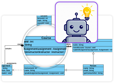
人工智能驱动的生成
高级功能包括人工智能功能,可从文本描述中即时生成专业的 ERD。人工智能可自动推断实体和外键约束,大幅减少手动设置时间。

双向同步
至关重要的是,该平台支持双向转换。这确保了视觉设计与物理实现保持同步,防止文档与实际代码库脱节的常见问题。
-
DBModeler AI 在模式设计中的全面评测:详细分析 DBModeler AI 如何通过自动化和智能化手段变革数据库模式设计。
-
DBModeler AI:智能数据库建模工具:访问 Visual Paradigm 中由人工智能驱动的工具,实现数据库建模与模式生成的自动化。
-
DBModeler AI:具备七步工作流程的人工智能驱动数据库设计工具。生成领域模型、ER 图、规范化模式及完整的设计报告。启动浏览器内实时数据库沙盒,立即测试查询。
-
人工智能文本分析——自动将文本转换为可视化模型:使用人工智能分析文本文档,并自动生成 UML、BPMN 和 ERD 等图表,以加快建模和文档编制速度。
-
Visual Paradigm ERD工具 – 在线创建实体-关系图:一款功能强大的基于网络的ERD工具,用户可通过直观的拖放功能轻松设计和可视化数据库架构。
-
使用ERD工具进行数据库设计 – Visual Paradigm指南:全面指南,介绍如何使用ERD工具以数据建模和架构设计的最佳实践来设计稳健且可扩展的数据库。
-
什么是实体-关系图(ERD)? – Visual Paradigm指南:对ERD的深入解释,包括其组成部分及其在数据库设计和数据建模中的重要性。
-
免费ERD工具 – 使用Visual Paradigm在线设计数据库:在线免费使用无需安装或订阅的ERD工具,创建专业的实体-关系图。
-
如何在Visual Paradigm ERD中绘制实体:逐步用户指南,介绍如何在Visual Paradigm的ERD工具中创建和自定义实体,以实现准确的数据库建模。
-
如何使用ERD建模关系型数据库 – Visual Paradigm教程:实用教程,展示如何使用ERD从概念到实现来建模关系型数据库。