


The Importance of Architectural Maturity in Database Design
Entity Relationship Diagrams (ERDs) serves as the backbone of effective system architecture. They are not static illustrations but are developed at three distinct stages of architectural maturity. Each stage serves a unique purpose within the database design lifecycle, catering to specific audiences ranging from stakeholders to database administrators. While all three levels involve entities, attributes, and relationships, the depth of detail and the technical specificity vary significantly between them.
To truly understand the progression of these models, it is helpful to use a construction analogy. Think of building a house: a Conceptual ERD is the architect’s initial sketch showing the general location of rooms like the kitchen and living room. The Logical ERD is the detailed floor plan specifying dimensions and furniture placement, though it does not yet dictate the materials. Finally, the Physical ERD acts as the engineering blueprint, specifying the exact plumbing, electrical wiring, and the specific brand of concrete for the foundation.

1. Conceptual ERD: The Business View
The Conceptual ERD represents the highest level of abstraction. It provides a strategic view of the business objects and their relationships, devoid of technical clutter.
Purpose and Focus
This model is primarily utilized for requirements gathering and visualizing the overall system architecture. Its main goal is to facilitate communication between technical teams and non-technical stakeholders. It focuses on defining what entities exist—such as “Student,” “Product,” or “Order”—rather than how these entities will be implemented in a database table.
Level of Detail
Conceptual models typically lack technical constraints. For example, many-to-many relationships are often depicted simply as relationships without the complexity of cardinality or join tables. Uniquely, this level may utilize generalization, such as defining “Triangle” as a sub-type of “Shape,” a concept that is abstracted away in later physical implementations.
2. Logical ERD: The Detailed View
Moving down the maturity scale, the Logical ERD serves as an enriched version of the conceptual model, bridging the gap between abstract business needs and concrete technical implementation.
Purpose and Focus
The logical model transforms high-level requirements into operational and transactional entities. While it defines explicit columns for each entity, it remains strictly independent of a specific Database Management System (DBMS). It does not matter at this stage whether the final database will be in Oracle, MySQL, or SQL Server.
Level of Detail
Unlike the conceptual model, the logical ERD includes attributes for every entity. However, it stops short of specifying technical minutiae like data types (e.g., integer vs. float) or specific field lengths.
3. Physical ERD: The Technical Blueprint
The Physical ERD represents the final, actionable technical design of a relational database. It is the schema that will be deployed.
Purpose and Focus
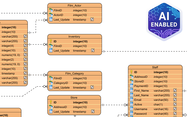
This model serves as the blueprint for creating the database schema within a specific DBMS. It elaborates on the logical model by assigning specific data types, lengths, and constraints (such as varchar(255), int, or nullable).
Level of Detail
The physical ERD is highly detailed. It defines precise Primary Keys (PK) and Foreign Keys (FK) to strictly enforce relationships. Furthermore, it must account for the specific naming conventions, reserved words, and limitations of the target DBMS.
Comparative Analysis of ERD Models
To summarize the distinctions between these architectural levels, the following table outlines the features typically supported across the different models:
| Feature | Conceptual | Logical | Physical |
|---|---|---|---|
| Entity Names | Yes | Yes | Yes |
| Relationships | Yes | Yes | Yes |
| Columns/Attributes | Optional/No | Yes | Yes |
| Data Types | No | Optional | Yes |
| Primary Keys | No | Yes | Yes |
| Foreign Keys | No | Yes | Yes |
Streamlining Design with Visual Paradigm and AI
Creating these models manually and ensuring they remain consistent can be labor-intensive. Modern tools like Visual Paradigm leverage automation and Artificial Intelligence to streamline the transition between these levels of maturity.
Model Transformation and Traceability
Visual Paradigm features a Model Transitor, a tool designed to derive a logical model directly from a conceptual one, and subsequently, a physical model from the logical one. This process maintains automatic traceability, ensuring that changes in the business view are accurately reflected in the technical blueprint.
AI-Powered Generation
Advanced features include AI capabilities that can instantly produce professional ERDs from textual descriptions. The AI automatically infers entities and foreign key constraints, significantly reducing manual setup time.

Bi-directional Synchronization
Crucially, the platform supports bi-directional transformation. This ensures that the visual design and the physical implementation stay in sync, preventing the common issue of documentation drifting away from the actual codebase.
-
Comprehensive Review of DBModeler AI for Schema Design: A detailed analysis of how DBModeler AI transforms database schema design through automation and intelligence.
-
DBModeler AI: Intelligent Database Modeling Tool: Access the AI-driven tool for automated database modeling and schema generation in Visual Paradigm.
-
DBModeler AI: AI-powered database design tool with 7-step workflow . Generate domain models, ER diagrams, normalized schemas, and complete design reports. Launch live in-browser database playground to test queries instantly.
-
AI Textual Analysis – Transform Text into Visual Models Automatically: Use AI to analyze text documents and automatically generate diagrams such as UML, BPMN, and ERD for faster modeling and documentation.
-
Visual Paradigm ERD Tool – Create Entity-Relationship Diagrams Online: A powerful, web-based ERD tool that enables users to design and visualize database schemas with ease using intuitive drag-and-drop features.
-
Database Design with ERD Tools – Visual Paradigm Guide: Comprehensive guide on using ERD tools to design robust, scalable databases with best practices in data modeling and schema design.
-
What is an Entity-Relationship Diagram (ERD)? – Visual Paradigm Guide: An in-depth explanation of ERDs, their components, and their importance in database design and data modeling.
-
Free ERD Tool – Design Databases Online with Visual Paradigm: Access a free, no-cost ERD tool online for creating professional entity-relationship diagrams without installation or subscription.
-
How to Draw Entities in Visual Paradigm ERD: Step-by-step user guide on creating and customizing entities in Visual Paradigm’s ERD tool for accurate database modeling.
-
How to Model a Relational Database with ERD – Visual Paradigm Tutorial: Practical tutorial showing how to use ERDs to model relational databases from concept to implementation.